
Owner`s manual
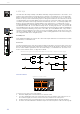


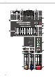
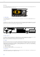
Table Of Contents
- 1 Introduction
- 2 Controls, Indicators and Connections
- 2.1 Input Mono
- 2.2 Input Stereo
- 2.3 FX 1/2
- 2.4 AUX
- 2.5 MON
- 2.6 MASTER with GEQ
- 37 - USB 2.0 DIGITAL AUDIO INTERFACE
- 38 - MASTER LED-DISPLAY
- 39 - STANDBY
- 40 - MASTER L/R fader
- 41 - MASTER A OUTPUTS L/R
- 42 - MASTER B OUTPUTS L/R
- 43 - MASTER B
- 44 - PRE/POST of MASTER B
- 45 - STEREO/MONO of MASTER B
- 46 - PHONES
- 47 - PHONES
- 48 - REC SEND L/R
- 49 - REC SEND & USB OUT
- 50 - 9-BAND STEREO GRAPHIC EQUALIZER
- 51 - USB INTERFACE
- 2.7 DISPLAY with function keys
- 2.8 Rear panel
- 3 Display & functions
- 4 DIGITAL AUDIO INTERFACE
- 5 Setting up a standard PA
- 6 Setup examples
- 1 Einführung
- 2 Bedienelemente und Anschlüsse
- 2.1 Input Mono
- 2.2 Input Stereo
- 2.3 FX 1/2
- 2.4 AUX
- 2.5 MON
- 2.6 MASTER mit GEQ
- 37 - USB 2.0 DIGITAL AUDIO INTERFACE
- 38 - MASTER-Aussteuerungsanzeige
- 39 - STANDBY-Schalter
- 40 - MASTER L/R-Fader
- 41 - MASTER A OUTPUTS L/R-Buchsen
- 42 - MASTER B OUTPUTS L/R-Buchsen
- 43 - MASTER B-Regler
- 44 - PRE/POST-Schalter für MASTER B
- 45 - STEREO/MONO-Schalter für MASTER B
- 46 - PHONES-Buchse
- 47 - PHONES-Regler
- 48 - REC SEND L/R-Buchsen
- 49 - REC SEND & USB OUT-Regler
- 50 - 9-BAND STEREO GRAPHIC EQUALIZER
- 51 - USB INTERFACE-Anzeige
- 2.7 DISPLAY mit Funktions-Tasten
- 2.8 Rückseite
- 55 - Netzbuchse
- Die Spannungsversorgung des CMS erfolgt ausschließlich mit dem mitgelieferten IEC-Netzkabel über eine verriegelnde Netzbuchse. Schließen Sie das CMS nur an eine geeignete Netzversorgung an, die den auf dem Typenschild angegebenen Anforderungen ent...
- 56 - Netzschalter (POWER)
- 57 - MIDI IN/OUT-Buchsen
- 3 Display & Funktionen
- 4 DIGITAL AUDIO INTERFACE
- 5 Aufbau einer Standard-PA
- 6 Aufbaubeispiele
- 7 Specifications

CMS
3
17
38 - MASTER LED-DISPLAY
The CMS offers two 10-segment LED-chains for optical monitoring the output levels of the L/R master signals. The indi-
cation range of the LED-meter is 40 dB, indicating the levels that are present at the master outputs in dBu. The meter’s
0 dB mark is referenced to a 0 dBu output signal at the mixer output. As soon as a PFL button is engaged, the PFL LED
lights. The meter instrument in the master section is simultaneously switched, so that the left LED-chain indicates the
level of the actually chosen channel (in dBu). The right LED-chain indicates the level of the summed post-fader master
output.
39 - STANDBY
Pressing the STANDBY switch mutes the output signals at the MASTER A OUTPUTS L/R, MASTER B OUTPUTS L/R, AUX
SEND and MONITOR outputs. The outputs REC SEND L/R and record channels of the DIGITAL AUDIO INTERFACE are
still operational. The STANDBY LED lights indicating that stand-by mode is engaged and that input channel signals are
not output via the speaker systems.
HINT: It is possible to playback the signal of stereo input 11-12 in standby mode. Therefore the entry Play 11-12 at
STDBY in the Device Setup menu must be enabled, see page 24 for details.
40 - MASTER L/R
FADER
Level controls to adjust the output signals of the left and right master outputs (MASTER A OUTPUTS L/R).
CAUTION: Please, make sure to set the input channel faders or at least the master faders to their minimum posi-
tion, or to engage the STANDBY switch, before connecting an external sound source to an input of the
CMS. This will save you, your audience, and the equipment from unnecessary stress.
41 - MASTER A OUTPUTS L/R
The mixer’s electronically balanced XLR (or unbalanced phone jacks) main outputs carrying the post master fader L/R
signals for connection of the main PA. The MASTER outputs are switched via output relay with a delay of approx. two
seconds after the mixer has been powered on, which prevents power-on noise when switching the mixer on or off.
Please also refer to the chapter “Setting up a standard PA system”.
42 - MASTER B OUTPUTS L/R
At the MASTER B OUTPUTS the L/R master audio signal is present that can be used for additional monitoring, side fill
and “next door” applications, or for the connection of a delay-line or subwoofer. The output is pre/post- and also stereo/
mono-switchable.
43 - MASTER B
This control allows adjusting the level of the MASTER B output. The signal levels at MASTER A OUTPUTS L/R and MAS-
TER B OUTPUTS L/R are identical if the MASTER B control is set to the position „5“ and the PRE/POST switch is set to
POST.
44 - PRE/POST
OF MASTER B
When PRE is selected the MASTER B is outputted pre master faders and pre GEQ, i.e. the level at the MASTER B OUT-
PUTS is independent from the master faders settings. When POST is selected the MASTER B is outputted post master
faders, i.e. the level at the MASTER B OUTPUTS depends on the setting of the master faders. Controlling a connected
Sub’s level via master fader makes sense when using an active subwoofer, so in this case select POST. For monitoring
applications, e.g. side fill on the stage, using the pre-fader setting seems more reasonable.
45 - STEREO/MONO
OF MASTER B
When STEREO is selected the MASTER L/R signal is not changed and outputted in stereo. When MONO is selected the
MASTER L/R signal is summed and outputted in mono at MASTER B L and also MASTER B R. Using MONO is recom-
mended when mono subwoofers are connected to MASTER B outputs.
46 - PHONES
Stereo phone jack (6.3 mm) for the connection of headphones with an impedance of 32 to 600 ohms. The audio signals
of the channels with PFL buttons engaged is outputted via this connector. The phones output presents the master A L/
R signal when there is no PFL button engaged. As the output is protected against short circuit, headphones or in ear
monitor systems with an impedance below 32 ohms can be connected. In this case the maximum reachable volume is
reduced.