OWNER’S MANUAL BEDIENUNGSANLEITUNG
DIGITAL SYSTEM AMPLIFIER CONTENTS Introduction . . . . . . . . . . . . . . . . . . . . . . . . . . . . . . . . . . . . . . . . . . . . . . . . . . . . . . . . . . . . . . . . . 5 Welcome . . . . . . . . . . . . . . . . . . . . . . . . . . . . . . . . . . . . . . . . . . . . . . . . . . . . . . . . . . . . . . . . . . . . . . . Unpacking and Inspection . . . . . . . . . . . . . . . . . . . . . . . . . . . . . . . . . . . . . . . . . . . . . . . . . . . . . . . . . . Scope of Delivery and Warranty . . . . . .
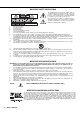
IMPORTANT SAFETY INSTRUCTIONS The lightning flash with arrowhead symbol, within an equilateral triangle is intended to alert the user to the presence of uninsulated „dangerous voltage“ within the product’s enclosure that may be of sufficent magnitude to constitute a risk of electric shock to persons. The exclamation point within an equilateral triangle is intended to alert the user to the presence of important operating and maintance (servicing) instructions in the literature accompanying the appliance. 1.
DIGITAL SYSTEM AMPLIFIER 1 Introduction 1.1 Welcome Thank you for choosing an Dynacord DSA series amplifier. Please take time to consult this manual so that you can understand all the features built into your Dynacord amplifier and fully utilize all its performance capabilities. 1.2 Unpacking and Inspection Carefully open the packaging and take out the power amplifier. Inspect the power amp’s enclosure for damages that might have happened during transportation.
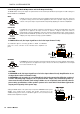
DIGITAL SYSTEM AMPLIFIER WARNING: The terminals marked with are hazardous live and the external wiring connected to these terminals requires installation by an instructed person or the use of ready-made leads of cords. HF-Interference (FCC Information USA) 1. IMPORTANT: Do not modify this unit! Changes or modifications not expressly approved by the manufacturer could void the user‘s authority, granted by the FCC, to operate the equipment. 2.
DIGITAL SYSTEM AMPLIFIER 2 Installation 2.
DIGITAL SYSTEM AMPLIFIER 2.2 Operating Voltage The power amplifier receives its power supply via the MAINS IN connector. Only the provided power cord may be used. During installation, always separate the power amplifier from the mains. Connect the power amplifier only to a mains network, which corresponds to the requirements indicated on the type plate.
DIGITAL SYSTEM AMPLIFIER CAUTION: Blocking/closing the power amp’s ventilation louvers is not permissible. Without sufficient cooling/ventilation, the power amplifier may automatically enter protect mode. Keep ventilation louvers free from dust to ensure unhindered airflow. Do not use the power amplifier near heat sources, like heater blowers, stoves or any other heat radiating devices. To ensure trouble-free operation, make certain that the maximum allowable ambient temperature of +40°C is not exceeded.
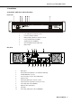
DIGITAL SYSTEM AMPLIFIER 2.9 Selecting the Mode Of Operation and Audio Output Cabeling The MODE switch on the power amp‘s rear panel defines how the audio inputs handle the input signals. Possible settings are DUAL, PARALLEL or BRIDGED. DUAL In DUAL mode, the two channels of the power amplifier work independent from each other. This mode of operation is being used for all 2-channel applications, like stereo operation.
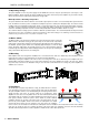
DIGITAL SYSTEM AMPLIFIER 2.10 Audio Input Cabeling Inputs are electronically balanced. Whenever possible, using balanced audio signal feeds at the input of the power amplifier is always preferred. Unbalanced connections should only be used if the cables are very short and no interfering signals are to be expected in the vicinity of the power amplifier. In this case, bridging the screen (shielding) and the pin of the inverting input inside of the connector is mandatory.
DIGITAL SYSTEM AMPLIFIER 3 Operation 3.1 Volume Control In DUAL and PARALLEL mode, the level controls LEVEL on the power amp’s rear panel are used to control the amplification of the corresponding channel. Turning the control to the right increases and turning it to the left decreases the volume. In BRIDGED mode operation, the output volume of the power amp is only controlled by the CH 1 level control. Any changes in the setting of the CH 2 level control are ignored. 3.
DIGITAL SYSTEM AMPLIFIER 3.3 Standby Mode (POWER REMOTE) POWER REMOTE provides a simple way to remotely power-on/off the power amplifier. The POWER REMOTE function is only useful for appliances not employing a Remote Control Modul. Controlling DSA amplifiers with Remote Control Module installed per POWER REMOTE is not recommended. Leaving the pins of POWER REMOTE socket open the appliance power is switched on. When connecting the pins the applicance enters standby mode. 3.
DIGITAL SYSTEM AMPLIFIER 4 Options Installing one of the optionally available extension modules in the extension slot on the rear panel lets you expand the power amp’s functional range. As an example, the following paragraphs describe the RCM-810 Remote Control Module. Please read and follow the instructions provided in the documentation that you have received together with each extension module. 4.
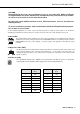
DIGITAL SYSTEM AMPLIFIER HIGH LOW Address HIGH LOW Address 0 0 Stand-alone 8 0...F 128...143 0 1...F 1...15 9 0...F 144...159 1 0...F 16...31 A 0...F 160...175 2 0...F 32...47 B 0...F 176...191 3 0...F 48...63 C 0...F 192...207 4 0...F 64...79 D 0...F 208...223 5 0...F 80...95 E 0...F 224...239 6 0...F 96...111 F 0...A 240...250 7 0...F 112...127 F B...F reserved Table 4.
DIGITAL SYSTEM AMPLIFIER Illustration 4.2: Pin-assignment of CAN jack and CAN plug Colour Pin Name 2 CAN_GND 4 CAN_H (+) Blue 5 CAN_L (-) Blue striped T568A T568B Green Orange Table 4.3: Overview CAN plug 4 CONTROL PORT The CONTROL PORT of the RCM-810 provides two control inputs, two control outputs and reference connections for +5V and ground. The control inputs are configurable via IRIS-Net™. They can be used for example for switching between power on / standby modes.
DIGITAL SYSTEM AMPLIFIER Owner‘s Manual 17
WICHTIGE SICHERHEITSHINWEISE Das Blitzsymbol innerhalb eines gleichseitigen Dreiecks soll den Anwender auf nicht isolierte Leitungen und Kontakte im Geräteinneren hinweisen, an denen hohe Spannungen anliegen, die im Fall einer Berührung zu lebensgefährlichen Stromschlägen führen können. Das Ausrufezeichen innerhalb eines gleichseitigen Dreiecks soll den Anwender auf wichtige Bedienungs- sowie Servicehinweise in der zum Gerät gehörenden Literatur aufmerksam machen. 1. 2. 3. 4. 5. 6. 7. 8. 9. 10. 11. 12.
DIGITAL SYSTEM AMPLIFIER 1 Einführung 1.1 Willkommen Vielen Dank, dass Sie sich für eine Endstufe der Dynacord Digital System Serie entschieden haben. Bitte lesen Sie diese Bedienungsanleitung aufmerksam durch, damit Sie Ihren neuen Dynacord Verstärker optimal nutzen können. 1.2 Auspacken und Inspektion Öffnen Sie die Verpackung und entnehmen Sie die Endstufe. Überprüfen Sie die Endstufe auf äußere Beschädigungen, die während des Transports zu Ihnen aufgetreten sein können.
DIGITAL SYSTEM AMPLIFIER 2 Installation 2.
DIGITAL SYSTEM AMPLIFIER 2.2 Betriebsspannung Die Spannungsversorgung der Endstufe erfolgt über den Anschluss MAINS IN ausschließlich über das mitgelieferte IECKabel. Trennen Sie die Endstufe während der Installation immer von der Netzversorgung. Schließen Sie die Endstufe nur an eine geeignete Netzversorgung an, die den auf dem Typenschild angegebenen Anforderungen entspricht.
DIGITAL SYSTEM AMPLIFIER ACHTUNG: Die Lüftungsöffnungen der Endstufe dürfen nicht blockiert/verschlossen werden. Bei fehlender Kühlung kann sich die Endstufe automatisch abschalten. Halten Sie alle Lüftungsöffnungen frei von Staubablagerungen, die den Luftstrom behindern würden. Betreiben Sie die Endstufe nicht in der Nähe von Wärmequellen wie Heizlüftern, Öfen oder anderen Geräten, die Hitze abstrahlen. Die maximale Umgebungstemperatur von +40°C soll für störungsfreien Betrieb nicht überschritten werden.
DIGITAL SYSTEM AMPLIFIER 2.9 Betriebsart (MODE) und Verkabelung des Audio-Ausgangs Der Schalter MODE an der Rückseite bestimmt die Betriebsart der Endstufe. Mögliche Schalterstellungen sind DUAL, PARALLEL und BRIDGED. DUAL In der Betriebsart DUAL arbeiten beide Kanäle der Endstufe unabhängig voneinander. Diese Betriebsart wird bei allen 2-kanaligen Anwendungen wie Stereobetrieb verwendet. Über die Eingangspegel-Regler an der Rückseite der Endstufe lässt sich die Verstärkung der Kanäle getrennt justieren.
DIGITAL SYSTEM AMPLIFIER 2.10 Verkabelung des Audio-Eingangs Die Signal-Eingänge INPUT sind elektronisch symmetrisch ausgelegt. Falls möglich, sollte stets ein symmetrisches Audiosignal am Eingang der Endstufe verwendet werden. Falls das/die Anschlusskabel sehr kurz sind und keine Störsignale in der Umgebung der Endstufe zu erwarten sind, kann auch ein unsymmetrisches Signal angeschlossen werden.
DIGITAL SYSTEM AMPLIFIER 3 Betrieb 3.1 Eingangspegel-Regler In den Betriebsarten DUAL und PARALLEL regeln die Eingangspegel-Regler LEVEL an der Rückseite der Endstufe die Verstärkung des jeweiligen Kanals. Drehung nach rechts erhöht die Lautstärke, Drehung nach links verringert die Lautstärke. In der Betriebsart BRIDGED regelt nur der Drehknopf von Kanal 1 (CH 1) die Lautstärke, die Drehknopf-Einstellung von Kanal 2 (CH 2) wird ignoriert. 3.
DIGITAL SYSTEM AMPLIFIER 3.3 Standby-Modus (POWER REMOTE) Über den Anschluss POWER REMOTE kann die Endstufe auf einfache Weise ferngesteuert ein- und ausgeschaltet werden. Die POWER REMOTE Funktion kommt nur bei Geräten ohne Remote Control Modul zum Tragen. Eine Steuerung von Geräten mit Remote Control Modul per POWER REMOTE ist nicht empfohlen. Werden die Pins der POWER REMOTE Buchse offen gelassen so schaltet das Gerät ein. Bei einer Verbindung der Pins schaltet das Gerät in den Standby-Modus. 3.
DIGITAL SYSTEM AMPLIFIER 4 Optionen Durch den Einbau eines optionalen Zusatzmoduls in den Erweiterungssteckplatz an der Rückseite kann der Funktionsumfang der Endstufe erhöht werden. Als Beispiel wird im folgenden das RCM-810 Remote Control Modul aufgeführt. Bitte beachten Sie bei allen Zusatzmodulen die jeweils mitgelieferte Bedienungsanleitung 4.1 RCM-810 Systembeschreibung Das RCM-810 Remote Control Modul ist ein Digital-Controller Modul für Live Sound, PA und Festinstallation.
DIGITAL SYSTEM AMPLIFIER 1 ADDRESS-Wahlschalter Mit den beiden Adress-Wahlschaltern wird die Netzwerk-Adresse des RCM-810 eingestellt. In einem CAN-Netzwerk können die Adressen 01 bis 250 (FA hex) verwendet werden. Die Adresseinstellung erfolgt im hexadezimalen Zahlensystem. Der Wahlschalter LOW ist für das niederwertige Digit, der Schalter HIGH für das höherwertige Digit. ACHTUNG: Jede Adresse darf im System nur einmal vorkommen, da es sonst zu Netzwerk-Konflikten kommt.
DIGITAL SYSTEM AMPLIFIER . Datenrate (in kbit/s) Buslänge (in m) 500 100 250 250 125 500 62,5 1000 20 2500 10 5000 Tabelle 4.2: Datenrate und Buslänge in CAN-Netzwerken Abbildung 4.2: Belegung der CAN-Buchse und des CAN-Steckers Kabelfarbe nach Pin Name 2 CAN_GND 4 CAN_H (+) Blau 5 CAN_L (-) Blau gestreift T568A T568B Grün Orange Tabelle 4.
DIGITAL SYSTEM AMPLIFIER Specifications/Technische Daten Amplifier at rated conditions, both channels driven, 8 Ω load, unless otherwise specified. DSA 8204 Load Impedance Maximum Midband Output Power THD = 1%, 1 kHz, Dual Channel Rated Output Power THD < 0.1%, 20 Hz...
DIGITAL SYSTEM AMPLIFIER 5.1 Mains Operation & Resulting Temperature DSA 8204 Umains in V Imains in A Pmains in W Pout in W Pd in W1 BTU/hr2 230 0.3 38 0 38 130 Max. Output Power @ 8 Ω3 230 4.9 800 540 260 887 Max. Output Power @ 4 Ω 230 8.0 1450 900 550 1877 1/3 Max. Output Power @ 4 Ω3 230 5.1 900 300 600 2047 1/8 Max. Output Power @ 4 Ω3 230 3.4 550 112.5 437.5 1493 1/8 Max. Output Power @ 4 Ω4 230 3.0 470 112.5 357.5 1220 1/8 Max.
DIGITAL SYSTEM AMPLIFIER DSA 8209 Umains in V Imains in A Pmains in W Pout in W Pd in W1 BTU/hr2 230 0.4 46 0 46 157 Max. Output Power @ 8 Ω3 230 9.4 1740 1100 640 2184 Max. Output Power @ 4 Ω 230 15.3 2810 1800 1010 3446 1/3 Max. Output Power @ 4 Ω3 230 8.7 1450 600 850 2900 1/8 Max. Output Power @ 4 Ω3 230 3.6 560 225 335 1143 1/8 Max. Output Power @ 4 Ω4 230 3.6 540 225 315 1075 1/8 Max. Output Power @ 4 Ω 253 4.
DIGITAL SYSTEM AMPLIFIER 5.
DIGITAL SYSTEM AMPLIFIER 5.
Americas Asia & Pacific Rim Bosch Communications Systems 12000 Portland Ave South Burnsville, MN 55337, USA USA: Japan: EVI Audio Japan Ltd. 5-3-8 Funabashi, Setagaya-Ku Tokyo, Japan 156-0055 Phone: +81 3-5316-5020 Fax: +81 3-5316-5031 China: Bosch Communications Systems Telex EVI Audio (Shanghai) Ltd. Room 3105-3109, No. 1 Building No.