
- Power Amplifiers Owner's Manual
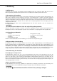

DIGITAL SYSTEM AMPLIFIER
16 Owner‘s Manual
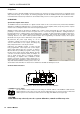
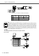
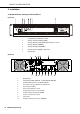
4 CONTROL PORT
The CONTROL PORT of the RCM-810 provides two control inputs, two control outputs and reference
connections for +5V and ground. The control inputs are configurable via IRIS-Net™. They can be used for
example for switching between power on / standby modes. The two control contacts IN1 and IN2 are
internally connected via pull-up resistors and carry +5V (open). The control inputs can be activated using
external switches, pushbuttons or relays to connect them to ground potential (pin 3). The two control outputs
OUT1 and OUT2 are open collector outputs, which are highly resistive in the non-active state (off). In active
state (on) the outputs are connected to ground. The control outputs are configurable via IRIS-Net™ and are
used to signal internal states. LEDs, indicators or relays can be driven directly. The +5V reference connector
provides voltage supply for connected components.
System Example
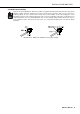
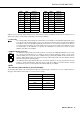
Illustration 4.2: Pin-assignment of CAN jack and CAN plug
Pin Name
Colour
T568A T568B
2 CAN_GND Green Orange
4CAN_H(+) Blue
5 CAN_L (-) Blue striped
Table 4.3: Overview CAN plug
CAUTION:
The maximally allowable current at the +5V output is 200 mA.