
Digital System Amplifier Owner's Manual

DIGITAL SYSTEM AMPLIFIER
6 Owner‘s Manual
2 Installation
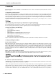
2.1 Controls, Indicators and Connections
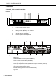
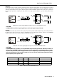
Front View
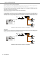
Rear View
1 Level Indicators for each channel
2 Protection Indicator (PROT) for each channel
3 Muting Indicator (MUTE) for each channel
4 Power On/Off Indicator (POWER)
5 Standby Indicator (STANDBY)
6 Remote Amplifier Indicator (IRIS-Net)
7 Mains Switch
1 Mains Input
2 POWER REMOTE connector (POWER REMOTE)
3 Power On Delay selection switch (ON DELAY)
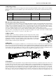
4 Power Amps Outputs (CH 1...4 / 5...8, BRIDGED)
5 Power Amp Outputs Mode Switch (MODE) and Outputs Load Switch (OUTPUT)
6 Input Level Control (LEVEL) for each channel
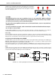
7 Audio Inputs (INPUT) for each channel
8 Expansion Slot (e.g. Remote Control Module RCM-810)
9 Type Plate