OWNER’S MANUAL BEDIENUNGSANLEITUNG
DIGITAL SYSTEM AMPLIFIER CONTENTS Introduction . . . . . . . . . . . . . . . . . . . . . . . . . . . . . . . . . . . . . . . . . . . . . . . . . . . . . . . . . . . . . . . . . . . . 4 Unpacking and Inspection . . . . . . . . . . . . . . . . . . . . . . . . . . . . . . . . . . . . . . . . . . . . . . . . . . . . . . . 4 Scope of Delivery and Warranty . . . . . . . . . . . . . . . . . . . . . . . . . . . . . . . . . . . . . . . . . . . . . . . . . . 4 Responsibility of the User . . . . . . . . . . . . . . .
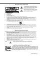
IMPORTANT SAFETY INSTRUCTIONS The lightning flash with arrowhead symbol, within an equilateral triangle is intended to alert the user to the presence of uninsulated „dangerous voltage“ within the product’s enclosure that may be of sufficent magnitude to constitute a risk of electric shock to persons. The exclamation point within an equilateral triangle is intended to alert the user to the presence of important operating and maintance (servicing) instructions in the literature accompanying the appliance. 1.
DIGITAL SYSTEM AMPLIFIER 1 Introduction Dynacord‘s new high efficiency DIGITAL SYSTEM AMPLIFIER series combine uncompromising audio performance with the highest reliabilty. 1.1 Unpacking and Inspection Carefully open the packaging and take out the power amplifier. Inspect the power amp’s enclosure for damages that might have occured during transportation. Each amplifier is examined and tested in detail before leaving the manufacturing site to ensure that it arrives in perfect condition at your place.
DIGITAL SYSTEM AMPLIFIER that interference will not occur in a particular installation.
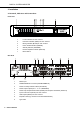
DIGITAL SYSTEM AMPLIFIER 2 Installation 2.1 Controls, Indicators and Connections Front View 1 Level Indicators for each channel 2 Protection Indicator (PROT) for each channel 3 Muting Indicator (MUTE) for each channel 4 Power On/Off Indicator (POWER) 5 Standby Indicator (STANDBY) 6 Remote Amplifier Indicator (IRIS-Net) 7 Mains Switch Rear View 6 1 Mains Input 2 POWER REMOTE connector (POWER REMOTE) 3 Power On Delay selection switch (ON DELAY) 4 Power Amps Outputs (CH 1...4 / 5...
DIGITAL SYSTEM AMPLIFIER 2.2 Operating Voltage The power amplifier receives its power supply via the mains input. During installation, always separate the power amplifier from the mains. Connect the power amplifier only to a mains network, which corresponds to the requirements indicated on the type plate.
DIGITAL SYSTEM AMPLIFIER ventilation. Since temperatures inside of the cabinet/rack case can easily rise up to 40 °C during operation of the power amp, it is mandatory to bear in mind the maximum allowable ambient temperature for all other appliances installed in the same cabinet/rack case. CAUTION: Blocking/closing the power amp’s ventilation louvers is not permissible. Without sufficient cooling/ventilation, the power amplifier may automatically enter protect mode.
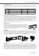
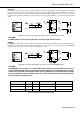
DIGITAL SYSTEM AMPLIFIER PARALLEL In PARALLEL mode, the inputs of channel A and channel B are directly electrically linked. The audio signal has to be applied to the input connectors of channel A. Using the input level controls to independently control the amplification of the two channels is still possible because only the channels’ inputs are linked. PARALLEL operation is the mode of choice, whenever the same input signal drives multiple power amp channels of a large system installation, e.g.
DIGITAL SYSTEM AMPLIFIER 2.7 Selecting the Mode of Output (OUTPUT) Different output modes are available for the amplifier‘s output channels. Each channel can be switched to high impedance mode (HZ) for driving 70 V or 100 V loudspeakers without output transformers (Direct Drive). In DUAL or PARALLEL mode each output channel‘s OUTPUT setting can be independently set.
DIGITAL SYSTEM AMPLIFIER 70 V Mode The 70 V mode allows connection of 70 V loudspeaker lines (Direct Drive) in high impedance mode (HZ) without using output transformers. In this case the maximum number of loudspeakers connected to an output channel is only limited by the amplifier‘s output power (500 W for DSA 8405/8805 or 1000 W for DSA 8410). This mode should be used if the distance between amplifier and speaker is larger than 50 metres (approx.
DIGITAL SYSTEM AMPLIFIER not affected by VLD. Power amplifier channels behave as described in chapter 2.7. The use of VLD considerably expands the adaptability of a power amplifier. Table 2.4 lists some application examples of VLD.
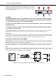
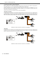
DIGITAL SYSTEM AMPLIFIER 2.10 Audio Cabling Input Inputs are electronically balanced. Whenever possible, using balanced audio signal feeds at the input of the power amplifier is always preferred. Unbalanced connections should only be used if the cables are very short and no interfering signals are to be expected in the vicinity of the power amplifier. In this case, bridging the screen (shielding) and the pin of the inverting input inside of the connector is mandatory.
DIGITAL SYSTEM AMPLIFIER 3 Operation 3.1 Volume Control In DUAL and PARALLEL mode, the level controls LEVEL on the power amp’s rear panel are used to control the amplification of the corresponding channel. The scale values are given in dB. Turning the control to the right increases and turning it to the left decreases the volume.
DIGITAL SYSTEM AMPLIFIER 4 Options Installing one of the optionally available extension modules in the extension slot on the rear panel lets you expand the power amp’s functional range. As an example, the following paragraphs describe the RCM-810 Remote Control Module. Please read and follow the instructions provided in the documentation that you have received together with each extension module. 4.
DIGITAL SYSTEM AMPLIFIER Controls and Connections Illustration 4.1: Controls and Connections of the RCM-810 1 INIT button The INIT button allows resetting the RCM-810 to factory settings. Press the button for at least 3 seconds using e.g. a small screwdriver. Table 4.1 lists the factory settings of the RCM-810 module. CAUTION: All RCM-810 parameters configured via IRIS-Net are discarded when pressing the INIT button.
DIGITAL SYSTEM AMPLIFIER 3 STATUS LED The STATUS LED is for monitoring the communication on the CAN bus. The LED blinks rhythmically every 3 seconds, when the module’s address is set to “00“, which means that it is disconnected from the CAN bus and software control. The LED blinks rhythmically in intervals of one second, when an address in the range of 01 to 250 has been assigned to the module and there has not yet been any activity on the CAN bus.
DIGITAL SYSTEM AMPLIFIER INHALT Einführung . . . . . . . . . . . . . . . . . . . . . . . . . . . . . . . . . . . . . . . . . . . . . . . . . . . . . . . . . . . . . . . . . . . . 20 Auspacken und Überprüfen . . . . . . . . . . . . . . . . . . . . . . . . . . . . . . . . . . . . . . . . . . . . . . . . . . . . . . 20 Lieferumfang und Garantie . . . . . . . . . . . . . . . . . . . . . . . . . . . . . . . . . . . . . . . . . . . . . . . . . . . . . . 20 Verantwortung des Betreibers . . . . . . . . . . . . . .
WICHTIGE SICHERHEITSHINWEISE Das Blitzsymbol innerhalb eines gleichseitigen Dreiecks soll den Anwender auf nicht isolierte Leitungen und Kontakte im Geräteinneren hinweisen, an denen hohe Spannungen anliegen, die im Fall einer Berührung zu lebensgefährlichen Stromschlägen führen können. Das Ausrufezeichen innerhalb eines gleichseitigen Dreiecks soll den Anwender auf wichtige Bedienungs- sowie Servicehinweise in der zum Gerät gehörenden Literatur aufmerksam machen. 1. 2. 3. 4. 5. 6. 7. 8. 9. 10. 11. 12.
DIGITAL SYSTEM AMPLIFIER 1 Einführung Mit den Endstufen der DSA-Serie von Dynacord beginnt ein neues Zeitalter in der Endstufen-Technologie. Die hocheffiziente Technik der DSA-Endstufe liefert kompromisslose Audioperformance bei geringem Gewicht und höchster Zuverlässigkeit. 1.1 Auspacken und Überprüfen Öffnen Sie die Verpackung und entnehmen Sie die Endstufe. Überprüfen Sie die Endstufe auf äußere Beschädigungen, die während des Transports zu Ihnen aufgetreten sein könnten.
DIGITAL SYSTEM AMPLIFIER 2 Installation 2.1 Bedienelemente, Anzeigen und Anschlüsse Frontseite 1 Pegelanzeige für Kanäle 1 bis 4 (DSA 8405/8410) bzw. 8 (DSA 8805) 2 Anzeige Schutzschaltung (PROT) 3 Anzeige Stummschaltung (MUTE) 4 Anzeige Betrieb (POWER) 5 Anzeige Standby (STANDBY) 6 Anzeige Remote Amplifier (IRIS-Net) 7 Netzschalter Rückseite 1 Netzeingang 2 POWER REMOTE-Buchse (POWER REMOTE) 3 Einschaltverzögerungs-Wahlschalter (ON DELAY) 4 Endstufenausgangsklemmen (CH 1...4 / 5...
DIGITAL SYSTEM AMPLIFIER 2.2 Betriebsspannung Die Spannungsversorgung der Endstufe erfolgt über die Netzeingangsbuchse. Trennen Sie die Endstufe während der Installation immer von der Netzversorgung. Schließen Sie die Endstufe nur an eine geeignete Netzversorgung an, die den auf dem Typenschild angegebenen Anforderungen entspricht.
DIGITAL SYSTEM AMPLIFIER Geräterückseite nicht behindert wird. Für den Einbau in Gehäuse und Racks ist zu beachten, dass eine ausreichende Belüftung der Endstufe möglich ist. Zwischen der Endstufen-Rückseite und der Schrank/Rack-Innenseite ist ein freier Luftkanal von mindestens 60 mm x 330 mm bis zur oberen Rack- oder Schrankentlüftung vorzusehen. Oberhalb des Schrankes soll ein freier Raum von mindestens 100 mm für die Entlüftung vorgesehen werden.
DIGITAL SYSTEM AMPLIFIER PARALLEL In der Betriebsart PARALLEL sind die Eingänge der Kanäle A und B direkt elektrisch verbunden (gelinkt). Das Eingangssignal ist über den Eingang des Kanals A zuzuführen. Da nur die Eingänge der beiden Kanäle miteinander verbunden sind, lässt sich weiterhin über die Eingangspegel-Regler die Verstärkung der beiden Endstufenkanäle getrennt einstellen.
DIGITAL SYSTEM AMPLIFIER 2.7 Wahl des Ausgangs-Modus (OUTPUT) Die Endstufenkanäle der Endstufen DSA 8405/8410/8805 können auf verschiedene Ausgangsmodi umgeschaltet werden. Bei Bedarf kann jeder Kanal einzeln auf Hochimpedanzbetrieb (HZ) umgeschaltet werden, um 70 V und 100 V Lautsprecherlinien direkt ohne Ausgangsübertrager (Direct Drive) anzutreiben. In den Betriebsarten DUAL und PARALLEL eines Ausgangskanal-Paares können die Ausgangs-Modi der Ausgangskanäle unabhängig voneinander eingestellt werden.
DIGITAL SYSTEM AMPLIFIER 70 V-Modus Der 70 V Modus erlaubt den direkten Antrieb (Direct Drive) von 70 V Lautsprecherlinien im Hochimpedanzbetrieb (HZ) ohne Ausgangsübertrager. Pro Kanal können dann maximal so viele Lautsprecher angeschlossen werden, bis die Gesamtleistungsaufnahme der Lautsprecherlinie dem Leistungswert des Verstärkers (500 W bei DSA 8405/8805 bzw. 1000 W bei DSA 8410) entspricht.
DIGITAL SYSTEM AMPLIFIER und 100 V verhalten sich unverändert wie in Kapitel 2.7 beschrieben. Durch die Verwendung von VLD erweitern sich die Anpassungsmöglichkeiten der Endstufe beträchtlich. Einige Anwendungsfälle von VLD finden sich in Tabelle 2.4.
DIGITAL SYSTEM AMPLIFIER 2.10 Audio Verkabelung Eingang Die Phoenix-Eingänge INPUT sind elektronisch symmetrisch ausgelegt. Wenn möglich, sollte stets ein symmetrisches Audiosignal am Eingang der Endstufe verwendet werden. Falls das/die Anschlusskabel sehr kurz sind und keine Störsignale in der Umgebung der Endstufe zu erwarten sind, kann auch ein unsymmetrisches Signal angeschlossen werden.
DIGITAL SYSTEM AMPLIFIER 3 Betrieb 3.1 Eingangspegel-Regler In den Betriebsarten DUAL und PARALLEL regeln die Eingangspegel-Regler LEVEL an der Rückseite der Endstufe die Verstärkung des jeweiligen Kanals. Die Skala ist in dB angegeben. Drehung nach rechts erhöht die Lautstärke, Drehung nach links verringert die Lautstärke. In der Betriebsart BRIDGED eines Ausgangskanal-Paares regelt nur der Drehknopf des Kanals mit ungerader Nummer (also 1, 3, 5 bzw.
DIGITAL SYSTEM AMPLIFIER 4 Optionen Durch den Einbau eines optionalen Zusatzmoduls in den Erweiterungssteckplatz an der Rückseite kann der Funktionsumfang der Endstufe erhöht werden. Als Beispiel wird im folgenden das RCM-810 Remote Control Modul aufgeführt. Bitte beachten Sie bei allen Zusatzmodulen die jeweils mitgelieferte Bedienungsanleitung 4.1 RCM-810 Systembeschreibung Das RCM-810 Remote Control Modul ist ein Digital-Controller Modul für Live Sound, PA und Festinstallation.
DIGITAL SYSTEM AMPLIFIER 1 INIT-Taste Die INIT-Taste erlaubt das Rücksetzen des RCM-810 auf die Werkseinstellungen. Betätigen Sie hierzu die Taste z. B. mit einem kleinen Schraubenzieher für mindestens 3 Sekunden. Tabelle 4.1 zeigt die zurückgesetzten Parameter. ACHTUNG: Alle Einstellungen des RCM-810, die Sie in IRIS-Net vorgenommen haben, werden bei Betätigung der INIT-Taste gelöscht.
DIGITAL SYSTEM AMPLIFIER 4 REMOTE CAN BUS-Anschlüsse Das RCM-810-Modul besitzt zwei RJ-45-Buchsen für den REMOTE CAN BUS. Die Buchsen sind parallel geschaltet und dienen als Eingang und zum Weiterschleifen des Remote-Netzwerkes. Zur Verkabelung innerhalb des Racks können handelsübliche RJ-45-Netzwerkkabel verwendet werden. Bei größeren Leitungslängen sind die CAN-Richtlinien zu beachten. Der CAN-Bus benötigt an beiden Enden einen 120 Ω Abschluss-Stecker.
DIGITAL SYSTEM AMPLIFIER Specifications/Technische Daten DSA 8405 Amplifier at rated conditions, all channels driven, rated loads, unless otherwise specified. Load Impedance Maximum Midband Output Power THD = 1%, 1 kHz, 4 channels driven Rated Output Power THD < 0.3%, 20 Hz6...20 kHz, 4 ch.
DIGITAL SYSTEM AMPLIFIER DSA 8410 Amplifier at rated conditions, all channels driven, rated loads, unless otherwise specified. Load Impedance Maximum Midband Output Power THD = 1%, 1 kHz, 4 channels driven Rated Output Power THD < 0.3%, 20 Hz6...20 kHz, 4 ch.
DIGITAL SYSTEM AMPLIFIER DSA 8805 Amplifier at rated conditions, all channels driven, rated loads, unless otherwise specified. Load Impedance Maximum Midband Output Power THD = 1%, 1 kHz, 4 channels driven Rated Output Power THD < 0.3%, 20 Hz6...20 kHz, 8 ch.
DIGITAL SYSTEM AMPLIFIER 5.1 Mains Operation & Resulting Temperature DSA 8405 Output Mode Umains in V Imains in A Pmains in W Pout in W Pd in all 230 1.1 120 0 120 409 1/8 Max. Output Power @ 2 Ω2 2Ω 230 3.7 490 4x63 238 812 1/8 Max. Output Power @ 4 Ω2 4Ω 230 3.4 465 4x63 213 727 70 V / 100 V 230 3.3 430 4x63 178 607 1/3 Max. Output Power @ 2 Ω2 2Ω 230 6.4 955 4x167 327 1116 1/3 Max. Output Power @ 4 Ω2 4Ω 230 6.3 925 4x167 257 877 70 V / 100 V 230 6.
DIGITAL SYSTEM AMPLIFIER DSA 8805 Output Mode Umains in V Imains in A Pmains in W Pout in W Pd in all 230 1.9 230 0 230 785 1/8 Max. Output Power @ 2 Ω2 2Ω 230 6.5 930 8x63 426 1454 1/8 Max. Output Power @ 4 Ω2 4Ω 230 6.0 860 8x63 356 1215 70 V / 100 V 230 5.6 800 8x63 296 1010 1/3 Max. Output Power @ 2 Ω2 2Ω 230 12.8 2045 8x167 709 2419 1/3 Max. Output Power @ 4 Ω2 4Ω 230 12.2 1920 8x167 584 1993 70 V / 100 V 230 11.
DIGITAL SYSTEM AMPLIFIER Block Diagram / Blockschaltbild 38 Owner‘s Manual / Bedienungsanleitung
DIGITAL SYSTEM AMPLIFIER 5.
DIGITAL SYSTEM AMPLIFIER Americas Asia & Pacific Rim Bosch Communications Systems 12000 Portland Ave South Burnsville, MN 55337, USA USA: Japan: EVI Audio Japan Ltd. 5-3-8 Funabashi, Setagaya-Ku Tokyo, Japan 156-0055 Phone: +81 3-5316-5020 Fax: +81 3-5316-5031 China: Bosch Communications Systems Telex EVI Audio (Shanghai) Ltd. Room 3105-3109, No. 1 Building No.