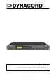
OWNER’S MANUAL DSP 244 24 BIT DIGITAL SOUND SYSTEM PROCESSOR 1-1
IMPORTANT SAFETY INSTRUCTIONS The lightning flash with arrowhead symbol, within an equilateral triangle is intended to alert the user to the presence of uninsulated “dangerous voltage” within the product’s enclosure that may be of sufficient magnitude to constitute a risk of electric shock to persons. The exclamation point within an equilateral triangle is intended to alert the user to the presence of important operating and maintance (servicing) instructions in the literature accompanying the appliance.
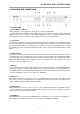
CONTENTS TABLE OF CONTENTS PAGE SAFETY AND SERVICE INSTRUCTIONS . . . . . . . . . . . . . . . . . . . . . . . . . . . . . . . . . . 1. INTRODUCTION . . . . . . . . . . . . . . . . . . . . . . . . . . . . . . . . . . . . . . . . . . . . . . . . . . . . 1.1 DSP 244 Features . . . . . . . . . . . . . . . . . . . . . . . . . . . . . . . . . . . . . . . . . 1.2 Unpacking and warranty . . . . . . . . . . . . . . . . . . . . . . . . . . . . . . . . . . . . . 2. CONTROLS AND CONNECTIONS . . . . . . . . . . . . .
INTRODUCTION 1. INTRODUCTION First of all, we would like to thank you for and congratulate you on buying the DYNACORD Digital Sound System Processor DSP 244. To ensure an optimum in the performance of the appliance and to prevent any damage resulting from erroneous or inadvertent handling or operation, please read this owner’s manual carefully, before operating the DSP 244. 1.
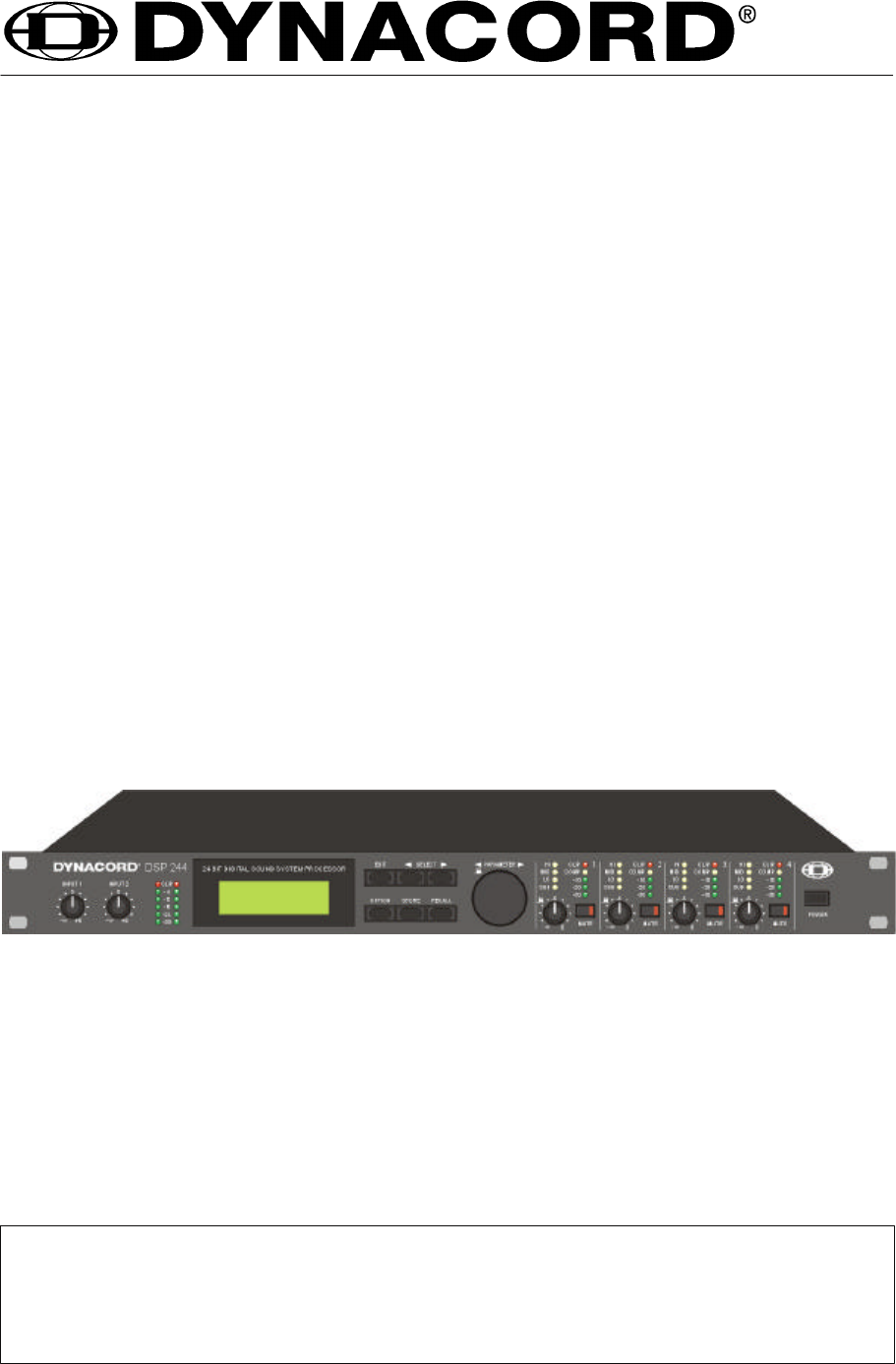
CONTROLS AND CONNECTIONS 2. CONTROLS AND CONNECTIONS 2.1 FRONT PANEL 1, Control INPUT 1 / INPUT 2 Rotary controls to set the input levels of the inputs 1 and 2 of the DSP 244. The input signal can be amplified by up to 6 dB (control set to its clockwise margin) or attenuated by any degree. Set the level as high as possible without clipping to achieve the highest possible S/N ratio. Checking your settings is possible via the reading of the two level meter instruments.
CONTROLS AND CONNECTIONS 8, STORE-key This key allows the user to store edited programs in one of the user-definable program presets (U01 U30) or to copy programs from one preset to another. For further information, please refer to chapter 7.4, “STORE PROGRAMS AND PROGRAM NAMES”. 9, RECALL-key Pressing this key lets you enter the PROGRAM SELECTION mode where you can select factory or user-definable program presets through using the rotary encoder.
CONTROLS AND CONNECTIONS 2.2 REAR PANEL 17, Mains connector Connect the supplied mains cord to the mains connector. The DSP 244 is capable of handling mains voltages between 90 V AC to 250 V AC, so that switching the mains on the appliance is not necessary. 18, RS-232 Interface This is the data communication interface between the DSP 244 and a PC. It allows unit configuration and editing by using the DSP 244 Editor software. At this position installation of optional interface boards is possible, also.
INSTALLATION AND CONNECTIONS 3. INSTALLATION AND CONNECTIONS Correct connections is a vital factor in achieving the best results with the DSP 244. Before switching on the power you have to connect the supplied European standard mains cord to the DSP 244 and your mains wall outlet. The power supply unit of the DSP 244 automatically adapts to supply voltages in a range of 90 to 250 VAC, so that the appliance can be operated with different, country-specific mains voltages.
FIRST OPERATION 4. FIRST OPERATION 4.1 SWITCHING THE POWER ON Using the POWER-switch (16) the DSP 244’s power is switched on. Upon initializing is complete, the last program that had been active before turning off the appliance is recalled. For now, the display shows: Now, the DSP 244 is ready for operation. The display shows for instance: Here, you have entered the factory preset program F01, which is an universal program for the 2-way operation.
QUICK START 5. QUICK START This paragraph describes in an overview the most important steps for a trouble-free operation of the DSP 244 in your PA-system. For a more detailed description of specific functions and parameters, please refer to the corresponding paragraph in the handbook. MAINS CONNECTION Plug in the supplied mains cord. Since the integrated power supply is capable of handling AC voltages between 90 V and 250 V, 50 / 60 Hz, within these limits no adjustments or switching is necessary.
QUICK START X-OVER SETTINGS In the Edit menu select the desired output channel by pressing the corresponding OUTPUT control. Then use the rotary encoder to select HIPASS XOVER in the display. Here you can set the low-cut frequency for the selected channel. Using the SELECT keys, you are able to select the parameters “Type” or “f” and edit their values through the use of the rotary encoder. After you are done, use the left SELECT key to re-position the cursor to the function block in the top line.
QUICK START COMPRESSOR / LIMITER SETTINGS A compressor / limiter automatically reduces level peaks above a certain threshold and therefore provides reliable protection against power amplifier clipping and damaging the connected loudspeaker systems. In most cases it is absolutely sufficient to set the compressor’s threshold to the modulation limit of the connected power amplifier. Select the desired output channel in the Edit menu by pressing the corresponding OUTPUT control.
CONFIGURATIONS OF THE DSP 244 6. CONFIGURATIONS OF THE DSP 244 The DSP 244 offers 7 pre-defined configurations. A configuration is a basic setting that includes the routing of inputs and outputs, the function of the outputs (Sub, Lo, Mid, Hi, Fullrange), as well as the kind and amount of parameters.
CONFIGURATIONS OF THE DSP 244 6.1 Stereo 2 Way This configuration generally represents a 2-way stereo frequency crossover, where IN 1 serves as the left input channel and IN 2 as the right input channel. OUT 1 is the left Low-range output and OUT 2 is the left High-range output. OUT 3 and OUT 4 are the corresponding right Low-range and High-range output channels. The parameters of the inputs 1 and 2 as well as the ones of the Low-range and High-range outputs are always set to identical values; i. e.
CONFIGURATIONS OF THE DSP 244 6.3 3 Way + Fullrange The 3-Way + Fullrange configuration is a 3-way monaural x-over with additional full range output where IN 1 serves as input channel. OUT 1 is the Sub-range channel, OUT 2 the Mid-range channel, OUT 3 the High-range channel, and OUT 4 is the Fullrange channel. OUT 4 can be used for example for monitoring, delayed full range-systems or to provide separate sound reinforcement in adjacent rooms.
CONFIGURATIONS OF THE DSP 244 6.5 3 Way / Independent Sub + Fullrange As well as the two previous configurations, this configuration also represents a 3-way frequency crossover with additional full range output, with the difference that the Sub-range channel OUT 1 gets its signal-feed from the input channel IN 2. Thus, it is independent from the other output channels. The audio signal for the outputs OUT 2 ... OUT 4 is fed from the input channel IN 1.
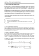
CONFIGURATIONS OF THE DSP 244 6.7 2-IN-4 In this configuration, all 4 outputs are configured for full range operation. OUT 1 and OUT 2 get their signal-feed from the input channel IN 1 while OUT 3 and OUT 4 are fed from the input channel IN 2. This structure is suitable for instance for the equalization of full range (wide-band) loudspeaker systems or passive multi-way systems. The following signal flow diagram shows the assignment of the inputs and outputs.
OPERATION 7. OPERATION The rotary encoder with push-button function for fast editing of parameter values, 6 function keys, and the push-button function of the output level controls OUT 1 - 4 are the main controls of the DSP 244. With EDIT, OPTION, STORE and RECALL you are able to branch off to and also return from the corresponding menus. The SELECT keys are used to choose between the different menu-pages or to select individual parameters. The rotary encoder lets you alter the parameter values.
OPERATION 7.1 PROGRAM SELECTION The DSP 244 offers 30 user-definable program presets (U01 - U30) and up to 50 factory pre-programmed presets (F01-F50). Altogether you have the possibility to choose from this selection of up to 80 different programs. CAUTION: A program also defines the configuration and therefore also assignment of the inputs and outputs of the DSP 244.
OPERATION 3. Whenever the function block in the first line is selected, you are able to select another function block by using the rotary encoder (10). Pressing one of the controls OUT 1 - 4 lets you directly select the function blocks of the corresponding output channel. 4. Using the SELECT keys (5) and (6) you are able to select the desired parameter and the rotary encoder (10) lets you alter the value of the selected parameter.
OPERATION 7.3 STORE PROGRAMS AND PROGRAM NAMES Whether you want to store an edited program, alter the name of a program, or copy a program from one preset location to another - in all cases the necessary procedure is the same. Pressing the STORE key (8) always starts and executes the saving procedure. You can also quit the Store menu without saving your result by pressing any other key. 1. Press the STORE key (8) to start saving a program . For instance, the display might look like this: 2.
OPERATION CAUTION! The program that was previously stored in this preset location is being erased! Please make sure, that the selected destination program number matches the number you want to save the program under. Pressing any other key cancels the saving procedure. After saving is complete, the Store menu is automatically quitted and the display might look for instance like this: 7.
PARAMETERS 8. PARAMETERS Depending on its configuration and operation mode, the DSP 244 offers a selection of more or less different parameters. The parameters are assigned to the input channels IN1, IN2, IN1+2 and to the 4 output channels OUT1, OUT2, OUT3, OUT4. The channel number is indicated in the top left corner of the display while the function block (MASTER EQ, MASTER DELAY, CHANNEL EQ, etc.) is shown next to the channel number.
PARAMETERS 8.1 PARAMETER ACCESS Depending on the actual configuration, only certain parameters are relevant. To provide a better overview and prevent erroneous operation, in the STANDARD Edit mode only those parameters are accessible. Additionally and to further improve operational comfort, corresponding parameters are linked. For Instance, in the Stereo 2-Way configuration, the Master EQs, the Master delays, the outputs OUT1 / OUT3 and OUT2 / OUT4, and the X-Over parameters are linked for mutual setting.
PARAMETERS 8.1.2 PARAMETER LINK-TABLE STANDARD Mode FULL EDIT Mode 1) Stereo 2 Way Stereo 2 Way / Mono Sub + Fullrange 3 Way + Fullrange 3 Way Mono Sub + Fullrange 3 Way Independ.
PARAMETERS Type describes the selected filter type. When selecting BYPASS, no effect is applied. PEQ provides a parametric Peak Dip Filter with programmable frequency, quality, and gain. LOSLV / HISLV stand for Low Shelving or High Shelving Equalizer, respectively. Their parameters are: frequency (f), slope, and gain. The parameters of the LOPASS / HIPASS filters are frequency and slope.
PARAMETERS PEQ: f = 1kHz, Gain = -12dB Q = 0.5, 1.0, 5.0, 20.0 Low Shelving Filter (LOSLV): High Shelving Filter (HISLV): f = 200Hz, Slope = 6dB f = 2000Hz, Slope = 6dB Gain = +3dB, +6dB, +9dB, +12dB Gain = +3dB, +6dB, +9dB, +12dB Low Shelving Filter (LOSLV): High Shelving Filter (HISLV): f = 200Hz, Slope = 12dB, f = 2000Hz, Slope = 12dB, Gain = +3dB, +6dB, +9dB, +12dB Gain = +3dB, +6dB, +9dB, +12dB Hi-Pass Filter (HIPASS): Lo-Pass Filter (LOPASS): f = 100Hz, Slope = 6dB, 12dB Q = 0.7, 1.0, 2.
PARAMETERS MASTER DELAY These delay lines are located in the inputs IN1, IN2 and in the summed input signal IN1+2; all x-over channels are affected. For instance, this allows to feed different PA-towers at open air concerts with delayed signals. The delay times are displayed in milliseconds and microseconds while the equivalent distances (unit) are displayed in feet, inches, meters or centimeters. The environmental temperature appears as additional parameter whenever distances are displayed.
PARAMETERS CHANNEL EQ1-4 The four output channels of the DSP 244 employ a 4-band parametric EQ each which allow to program additional equalization for the individual frequency ranges. This guarantees the optimum frequency response that is matched to the connected loudspeaker components. Parameter Type Settings / Value range Default BYPASS, PEQ, LOSLV, HISLV, HIPASS, LOPASS, ALLPASS BYPASS PEQ f Q Gain 20Hz - 20kHz 0.4 - 20.0 -12dB - +12dB 1.00 kHz 0.
PARAMETERS Gain sets the degree of amplification or attenuation of the parametric EQ or the low shelving and high shelving equalizers. The setting is performed in steps with 1 dB-stepwidth. The Slope parameter describes the steepness or order of the filter for the low shelving or high shelving equalizers.
PARAMETERS HIPASS X-OVER The frequency crossover filter consists of a low pass filter in one channel and a high pass filter in the adjacent channel. Here, the frequency x-over filter’s Hi-Pass parameters are set. The parameters of the corresponding Lo-Pass should be set to the same values. An x-over filter provides the parameters “Type” and “f”. Parameter Default Settings / Value range Type thru, 6 dB, 12dB Q0.5, 12dB Q0.6, 12dB Q0.7, 12dB Q0.8, 12dB Q1.0, 12dB Q1.2, 12dB Q1.5, 12dB Q2.
PARAMETERS The f parameter (frequency) sets the x-over Lo-Pass filter’s cutoff frequency. The corresponding Hi-Pass filter should be set to the same cutoff frequency. Pol defines the polarity of the corresponding channel. Depending on the characteristic of the frequency crossover filter, inverting the polarity of a channel’s signal may become necessary; i. e.: set a negative polarity.
PARAMETERS CHANNEL DELAY These delays are provided in the output channels OUT1 - OUT4. They are used to compensate differences in loudspeaker dispersion plains that can be cabinet imminent or result from the positioning of individual loudspeaker cabinets or arrays. The delay time or acoustical distance is displayed in milliseconds, microseconds, feet, inches, meters, or centimeters. The environmental temperature appears as additional parameter whenever distances are displayed.
PARAMETERS COMPRESSOR The compressor automatically reduces level peaks above a certain threshold and therefore provides reliable protection against power amplifier clipping and damaging the connected loudspeaker systems. Parameter Default Settings / Value range Thrsh 0.27V - 8.70V 8.70V Rat 1/1.0, 1/1.4, 1/2.0, 1/4.0, 1/8.0 1/2.0 Attack 0ms - 99ms 5 ms Rels 50ms - 999ms 250 ms The Thrsh parameter (Threshold) defines the level at which the compressor starts operating.
PARAMETERS LIMITER The limiter provides additional protection against the occurrence of clipping and overload conditions. The maximum level of the audio signal is limited to the set threshold value. The short attack times guarantee that even sudden peak levels are effectively attenuated. Parameter Settings / Value range Default Thrsh 0.27V - 8.70V 8.70V Release 50ms - 999ms 100ms The Thrsh parameter (Threshold) defines the level at which the limiter starts operating.
OPTION 9. OPTION FUNCTIONS The “option programs” offer several additional, important information and preference settings for the DSP 244.
OPTION 9.3 COMPRESSOR AND LIMITER THRESHOLD UNIT This function allows setting the unit of the compressor and limiter threshold. Volts: The threshold value is displayed in volts. dBu (0.775 V): The threshold value is displayed in dBu (0dBu = 0.775V). dB from Clip: Threshold setting in dB relative to full modulation. (0 dB = full modulation). 9.4 VU LEVEL METER DISPLAY MODE Normal fast: The peak hold function is off; the levels are displayed with a short drop rate of approximately 600 dB/s.
OPTION The following safety dialog appears: ARE YOU SURE? PRESS STORE TO CONFIRM ! Press the STORE twice to acknowledge this dialog. When trying to change one of the appliance’s settings, SYSTEM IS LOCKED! appears on the display, indicating that the DSP 244’s operating system is blocked for entries via the numeric keys or the rotary encoder. To disable edit-protection, select the “LOCK CODE” page in the OPTION mode again.
OPTION You can select one of the following settings for the MIDI TX CHANNEL: Off: No MIDI DATA is transmitted. 1 - 16: The DSP 244 transmits MIDI DATA via the selected MIDI channel 1 to 16. 9.8 SEND PARAMETERS During editing or when sending a program change command, the DSP 244 is capable of transmitting its parameters in real time via the serial port(s). A complete parameter dump of the new program is automatically carried out during program changes.
OPTION Off: No RS-232 data is transmitted via MIDI ports. On: Data that is received from the RS-232 port is passed on to linked units via the MIDI port and is transmitted using the previously selected MIDI transmission channel (MIDI TX CHANNEL). 9.10 NRS 90246 CONTACT CLOSURE INTERFACE settings Amongst others, the DSP 244 is prepared for retrofitting an optional NRS 90246 Contact Closure Interface, which can be used instead of the RS-232 interface.
OPTION CNTCT: 1 Here you are able to select the control input (1 - 8) for programming. PGM: U01 In this case, the selected control input is used for program change commands. You are able to select user-programs U01 to U30 or factory-presets F01 to F50. PGM: Mute This setting allows to use the selected control input for Soft-Mute. Upon closing of the corresponding contact, the DSP 244 outputs are muted - upon opening, the signal is “softly” switched on again.
SPECIFICATIONS 10. SPECIFICATIONS 10.1 TECHNICAL SPECIFICATIONS Mains voltage Power consumption Safety class 90 - 250 V AC / 50 - 60 Hz 20 watts I Inputs Input voltage (nominal) Max. input voltage Input impedance Common mode rejection AD-conversion 2 x XLR IN, electronically balanced, transformer optional available 2 x XLR OUT (Direct Out) 1.55 V / + 6 dBu 24.5 V / + 30 dBu 20 kohms > 70 dB (1kHz) 24-bit, Sigma-Delta, 128 times oversampling, linear phase Outputs Output voltage (nominal) Max.
M IDI 10.2 MIDI This chapter provides information (all implemented MIDI transmission commands) for the experienced software programmer that wants to design new software for the DSP 244. The implementation chart is relevant for the software revision V1.0 or higher. MIDI data transfer is possible, only when a MIDI channel is activated (OMNI, 1 - 16). See also chapter 9.7, MIDI RX / TX CHANNEL settings. 10.2.
M IDI Serial Link (recognized + transmitted) MIDI-Byte Beschreibung System Exclusive DYNACORD ID: No 48 n = MIDI Channel 0 - 15 (7F = All Channels) DSP 244 ID: No 24 Function ID: Serial Link / Parser ASCII Code Line for Command Parser (up to 120 Byte) Checksum for DATA (7 Bit, 2’s Complement) End of SysEx Message F0 (hex) 30 0n 18 01 DATA CHECKS F7 Further details concerning the Command Parser ASCII Code are shown in the following tables.
Command Parser Code Table UNIT-ID Tree Value Unit DELAY 1.927... 900.0 ms FREQ 20 ... 20000 Hz GAIN -12 ...12 dB QUAL 0.4 ... 20.0 /ID1/ IN1/ EQ1/ SLOPE 6,12 TYPE BYPASS,PEQ,LOSLV, HISLV,HIPASS,LOPASS EQ2/ ... EQ5/ dB/Octave see EQ1/ IN2/ see IN1/ INSUM/ DELAY 1.927 ... 900.0 ms FREQ 20 ... 20000 Hz GAIN -12 ... 12 dB QUAL 0.4 ... 20.0 OUT1/ EQ1/ SLOPE 6,12 *) TYPE BYPASS,PEQ,LOSLV, HISLV,HIPASS,LOPASS, ALLPASS EQ2/ ...
RETROFITTING INSTRUCTIONS 10.3 RETROFITTING INSTRUCTIONS CAUTION: These servicing instructions are for use by qualified personnel only. To reduce the risk of electric shock, do not perform any servicing other than that contained in the Operating Instructions unless you are qualified to do so. Refer all servicing to qualified service personnel. 10.3.1 Installation manual for the input transformer (NRS 90244, EDP-No.
RETROFITTING INSTRUCTIONS 10.3.2 Installation manuals for interface cards: Contact Closure Interface RS-485 Interface (NRS 90246, EDP-No. 112766) (NRS 90247, EDP-No.
BLOCKDIAGRAMM / BLOCK DIAGRAM 10-7
FLUSSDIAGRAMM / FLOW DIAGRAM 10-5
ABMESSUNGEN / DIMENSIONS Abmessungen / Dimensions (in mm) 10-6
GARANTIE WARRANTY GARANTIE Das Werk leistet Garantie für alle nachweisbaren Material- und Fertigungsfehler für die Dauer von 36 Monaten ab Verkauf. Garantieleistungen werden nur dann anerkannt, wenn gültige, d.h. vollständig ausgefüllte Garantieunterlagen vorliegen. Von der Garantie ausgenommen sind alle Schäden, die durch falsche oder unsachgemäße Bedienung verursacht werden. Bei Fremdeingriffen oder eigenmächtigen Änderungen erlischt jeder Garantieanspruch.