INTRODUCTION 1. INTRODUCTION Preamble Thank you for choosing the DYNACORD PROANNOUNCE System. With the PROANNOUNCE System you purchased a high-quality product which is going to satisfy your highest demands. This extraordinarily flexible and versatile system allows the configuration of either small or complex installations as well. Most functions are realized through software modules, which - when compared to conventional PA-systems – not only reduces the amount of cabling but also the costs.
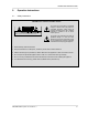
OPERATION INSTRUCTIONS 2. Operation Instructions 2.1 Safety Instructions IMPORTANT SAFETY INSTRUCTIONS CAUTION RISK OF ELECTRIC SHOCK DO NOT OPEN WARNING: DO NOT EXPOSE THIS APPLIANCE TO RAIN OR MOISTURE. AVIS: RISQUÉ DE CHOC ELECTRIQUE. NE PAS OUVRIR. The symbol of a flash within an equilateral triangle is to alert the user to the presence of uninsulated dangerous voltage within the product's enclosure that may be of sufficient magnitude to constitute a risk of electric shock to persons.
OPERATION INSTRUCTIONS CAUTION ! 1. To prevent the risk of fire and shock hazard, do not expose any appliance or module high humidity or water. 2. Make sure that no alien objects enter the appliances or get in contact with the modules – especially no metal parts – since this would very likely cause dangerous electric shock and/or malfunctioning. There are no userserviceable parts located inside the appliances or on the modules.
OPERATION INSTRUCTIONS 2.2 Operation Instructions 2.2.1 Central Unit DPM 4000 According to its specified capabilities and specifications, the DPM 4000 central unit can be used to control and monitor PA- and paging systems in buildings, but also to operate professional audio systems. The DPM 4000 central unit is not an independent device. For its operation, at least the following is necessary: 1.
OPERATION INSTRUCTIONS 2.2.2 DPA 4000 Power Amplifier Especially designed for it, the DPA 4000 Series power amplifiers optimally match the PROANNOUNCE system. Thus guaranteeing trouble-free installation and operation. The power amplifiers are "stand alone" devices, offering the opportunity for them to be operated together with several other pieces of equipment, as long as all valid specifications and applicable instructions for the installation are being observed. 2.2.
OPERATION INSTRUCTIONS 2.3 Operation Location The appliances are exclusively meant for the installation in 19" rack shelf systems while the modules can also be installed in an appropriate wall junction box. When installing the system, the safety regulations that are mentioned in chapter 2.1 have to be observed.
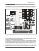
SYSTEM DESCRIPTION 3. System Description This chapter provides an overview of the general configuration of the PROANNOUNCE system and its most important functions. The following block diagram shows a typical PROANNOUNCE system installation including the DPM 4000 central unit, paging stations, audio equipment, amplifiers, power supply unit, relay board assemblies, loudspeaker lines, and control board assemblies for external signals. figure 3.1 PROANNOUNCE System 3.
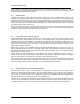
SYSTEM DESCRIPTION normal operation, PC-interaction is not necessary. Anyway, in most cases the permanent connection of a computer bears benefits, like displaying detailed status reports or the printing of protocols. It also offers the possibility for remote diagnosis and remote maintenance via modem. 3.2 Audio Routing The DPM 4000 employs a digital audio matrix providing 4 inputs and 4 outputs.
SYSTEM DESCRIPTION 3.5 Paging Stations The DPC 4000 Series paging consoles are mainly meant for transmitting voice messages and calls but also to manually control the PROANNOUNCE system. Available paging station functions are: line/group selection, voice messages, program assignment, launching gong and alarm signals, and reproduction of voice message memory announcements.
SYSTEM DESCRIPTION 3.9 Macros Macro is defined as the combination of several commands, functions, and their parameters in an internal consecutive sequence. For example a gong signal with specific volume and priority settings has to be transmitted in different calling zones, while simultaneously activating a control output.
INSTALLATION 4. Installation The PROANNOUNCE Designer software has been designed for use on computers running Microsoft Windows95/98/NT and utilizes all typical features of these operating systems. Therefore it is important that the user is familiar with using application software running under Windows. 4.1 Installation And Program Start 4.1.1 System Specifications The software can be used on a desktop or laptop PC running Windows95/98/NT as operating system.
INSTALLATION 4.1.3 Starting PROANNOUNCE Designer Windows95/98/NT offers several choices to start the PROANNOUNCE Designer software: - Select EXECUTE within the Windows95/98/NT start menu, enter the command line "C:\programs\PROANNOUNCE\PROANNOUNCE.exe" and confirm with OK. - In the Windows95/98/NT start menu, select programs/PROANNOUNCE and click onto PROANNOUNCE Designer. - Link the "PROANNOUNCE.exe" file onto your desktop and start the program by double clicking the PROANNOUNCE Designer icon.
DEVICE DESCRIPTIONS 5. Description Of Individual Devices 5.1 Digital PROANNOUNCE Manager DPM 4000 5.1.1 Features The Digital PROANNOUNCE Manager DPM 4000 represents the central unit of the PROANNOUNCE system incorporating all primary functions that are needed in advanced PA-system installations.
DEVICE DESCRIPTIONS The following block diagram outlines the features once again. It shows a DPM 4000 equipped with a 2-channel paging station module (NRS 90215), a MIC/LINE + 2 AUX inputs module (NRS 90216), two 2-channel LINE output modules (NRS 90218) and an 8 I/O control module (NRS 90219). The ports of the interface block are standard. Their functioning is explained in detail on the following pages.
DEVICE DESCRIPTIONS 5.1.2 Front View figure 5.2 DPM 4000 front view The following controls and indicators are located on the DPM 4000's front panel: 1. LED DCF 77 This LED indicates the operation mode of the DCF 77 radio-controlled-signal receiver. The following table shows the different indications and explains their corresponding status: LED indication OFF status No radio control signal detected or no DCF 77 antenna connected. The system clock is quartz-synchronized.
DEVICE DESCRIPTIONS 5.1.3 Rear View 5 WARNING: TO REDUCE THE RISK OF FIRE OR ELECTRIC SHOCK, DO NOT EXPOSE THIS APPLIANCE TO RAIN OR MOISTURE. DPM - LC 8 4 3 DPM - OUT 2 OUT C O N T R O L 121619 CAUTION: SEE OPERATION MANUAL FOR MODULE SIGNAL INTERFACE MADE IN GERMANY DC INPUT 24 + -- 1 + 24 V 2 GROUND 3 READY 4 5 FITTING AND CORRECT CABLES AND CONNECTION.
DEVICE DESCRIPTIONS 3. RS-232 PC INTERFACE This 9-pole PC-interface is meant for connecting a computer (female, pin 4 = TXD, pin 3 = RXD, pin 1 = ground). It is used to transfer data between the PC and the DPM 4000 during system configuration as well as for control, monitoring, and remote diagnosis purposes. The PC is connected to the DPM 4000 utilizing a standard 1:1 D-sub extension cord with male connectors on one end and female connectors on the other.
DEVICE DESCRIPTIONS 5. MONITOR OUTPUT socket The audio signal of the integrated monitor amplifier is outputted via this connector. In standard configuration, this output is set for the connection of headphones. It is also possible to directly connect a loudspeaker with minimum load impedance of 8 Ohms. To achieve higher output capacity it is possible to set the internal monitor amplifier to bridged operation. Thus some internal jumpers have to be re-set as shown in the figure below.
DEVICE DESCRIPTIONS 5.1.4 Specifications Supply voltage Nominal power consumption Maximum power consumption 24 V DC (21.6 ... 31.2 V DC) 500 mA 6.7 A Audio section Inputs Outputs Frequency Response S/N ratio Distortion see specifications of the corresponding input module see specifications of the corresponding output module 20 Hz ... 20 kHz, ± 0.5 dB > 100 dB (A-weighted) < 0.
DEVICE DESCRIPTIONS 5.1.5 2-Channel Paging Station Module (NRS 90215) This 2-channel audio input module is meant for the connection of DPC 4000 Series paging consoles. Each of the two input channels provide RJ-45 sockets allowing the connection of up to 4 paging stations plus paging station extensions per input. The microphone terminals are interconnected via 6-conductor parallel cables. The module can be installed in slot 1 and slot 2.
DEVICE DESCRIPTIONS Pin-Assignment Of DPC 4000 Connectors And The Extension Cord: Connecting DPC 4000 paging stations to the DPC 4000 IN connector is established through the use of common RJ-45 extension cords, where the conductors are twisted in pairs as follows: pair 1 = 1/2 (24 V/GND), pair 2 = 3/6 (free), pair 3 = 4/5 (RS-485), pair 4 = 7/8 (AUDIO). AUDIO IN AUDIO IN + RS- 485 RS- 485 + GND + 24V RJ- 45 extension cord DPC 4000 IN 8 8 7 6 5 4 3 2 1 AUDIO RS- 485 1 24V/GND figure 5.
DEVICE DESCRIPTIONS Retrofitting Input Transformers: In case galvanic separation of the audio signal is necessary, the module is prepared for retrofitting two input transformers. Separate NRS 90208 extensions consisting of audio transformer and insulation plate each are needed per input channel. When retrofitting the transformers, please proceed as follows: 1. 2. 3. 4. 5. 6. Disconnect the DPM 4000 from the mains power supply. Loosen the two locking screws and carefully slide the module out of the slot.
DEVICE DESCRIPTIONS 5.1.6 MIC/LINE + 2 AUX Input Module (NRS 90216) This 2-channel audio input module is meant for the connection of external audio sources of any kind. Channel A employs two switched AUX-inputs with 4 RCA-type connectors (2 x L / R) for CD players, tape decks, tuners, DAT decks, etc. The MIC / LINE-input of channel B is provided through an XLRF-type connector allowing the connection of microphones, mixers and other similar sources. The module can be inserted in slot 1 and slot 2.
DEVICE DESCRIPTIONS Pin-Assignment Of XLRF-Type Connectors: The pin-assignment of the MIC/LINE input's XLRF-type connector is as follows: pin 1 = screen, pin 2 = positive conductor, pin 3 = negative conductor. In unbalanced configuration, the pins 3 (-) and 1 (screen) have to be bridged inside the connection plug. 1 SHIELD -+ 3 2 BALANCED LO (-) SOURCE HI (+) MIC/ LINE IN figure 5.
DEVICE DESCRIPTIONS In addition, a MIC/LINE jumper (JP1, pins 5-6) is located on the printed board assembly, which allows correctly configuring the input. When changing the MIC/LINE switch it is important to change the jumper correspondingly (open = LINE, closed = MIC). When shipped, the factory preset is: switch S1 in the LINE position and jumper JP1 open.
DEVICE DESCRIPTIONS 5.1.7 2-Channel MIC/LINE Input Module (NRS 90217) This 2-channel audio input module is meant for the connection of external audio sources, like microphones, mixers, etc. Both channels are furnished with XLRF-type connectors. The module can be installed into slot 1 and slot 2. The sensitivity of the MIC / LINE inputs can be adjusted in a wide range. The internal MIC / LINE switches (PADs) provide 30 dB attenuation.
DEVICE DESCRIPTIONS Pin-Assignment Of XLRF-Type Connectors: The pin-assignment of the MIC/LINE input's XLRF-type connector is as follows: pin 1 = screen, pin 2 = positive conductor, pin 3 = negative conductor. In unbalanced configuration, the pins 3 (-) and 1 (screen) have to be bridged inside the connection plug. 1 SHIELD -+ 3 2 BALANCED LO (-) SOURCE HI (+) MIC/ LINE IN figure 5.
DEVICE DESCRIPTIONS 2. Phantom Power By closing the jumpers JP1, pins 1-2 and pins 3-4 (IN A) respectively JP2, pins 1-2 and pins 3-4 (IN B), it is possible to (separately) engage 24 V phantom power when a microphone is connected to the corresponding input. When shipped, jumpers are set to “open” (no phantom power). 3.
DEVICE DESCRIPTIONS 5.1.8 2-Channel AUX Input Module (NRS 90228) This 2-channel audio input module provides 8 RCA-type connectors (4 x L / R) for connecting external audio sources such as CD-players, tape decks, tuners, DAT decks, etc. The module can be installed into slot 1 and slot 2. The input levels of the four AUX inputs can be independently adjusted in a range between -10 dBu and +12 dBu via internal trim-potentiometers.
DEVICE DESCRIPTIONS Block Diagram: +24V AUX 1 GAIN L +12V AUX 1 +5V R IN A DIGITAL SUPPLY INTERNAL MONITOR AUX 2 GAIN L ANALOG SUPPLY -12V AUX 1 MON A PILOT AUX 2 AUX 2 MCLK R A BCLK WCLK D PILOT A 2 CHANNEL DIGITAL AUDIO DIN MON B 4 BOARD CONTROL PILOT B SPI AUX 3 GAIN L AUX 3 RES AUX 3 R BOARD STATUS & ID IN B AUX 4 GAIN L AUX 4 AUX 4 R figure 5.
DEVICE DESCRIPTIONS 5.1.9 MIC/LINE + Paging Station Module (NRS 90234) This 2-channel audio input module is meant for the connection of DPC 4000 Series paging stations and other external audio sources. The RJ-45 socket of channel A allows the connection of up to 4 microphone terminals plus paging station extensions. The MIC / LINE input of channel B is furnished through an XLRF-type connector allowing the connection of microphones, mixers and other audio signal sources.
DEVICE DESCRIPTIONS supply output for the DPC 4000 supply voltage nominal current power consumption operational temperature range dimensions W x H x D weight extensions 1, short-circuit-proof, electronic, programmable fuse 24 V DC (21.6 ... 31.2 V DC) 330 mA, 660 mA, 990 mA (set via electronic fuse) 2.5 W +5 °C ... +40 °C 37.5 x 81 x 252 mm 165 g (215 g including NRS 90208 + NRS 90233) NRS 90208 input transformer for 1 paging station input, order No.
DEVICE DESCRIPTIONS Block Diagram: ELECTRONIC PROGRAMMABLE FUSE +U24 +12V ANALOG SUPPLY -12V +5V DPC 4000 IN A 24V RS-485 AUDIO DIGITAL SUPPLY RX485 TX485 NRS 90208 INTERNAL MONITOR MON A PILOT MCLK A PILOT A BCLK WCLK D 2 CHANNEL DIGITAL AUDIO DIN +24V JP1 1 2 3 4 MIC/ LINE IN B MON B MIC LINE 1 BOARD CONTROL PILOT B 4 SPI GAIN 2 3 RES NRS 90233 JP2 LIN COMP LINE MIC JP1 BOARD STATUS & ID 5 6 COMPRESSOR / LIMITER figure 5.
DEVICE DESCRIPTIONS Retrofitting Input Transformers: Retrofitting two input transformers onto the module is possible for the case that galvanic separation of the audio signals is needed. For the DPC 4000 input a NRS 90208 extension is needed, which consists of an audio transformer and an insulation plate. For the MIC/LINE input a NRS 90233 extension is needed. When retrofitting input transformers, please proceed as follows: 1. 2. 3. 4. 5. 6. Disconnect the DPM 4000 from the mains power supply.
DEVICE DESCRIPTIONS 5.1.10 2-Channel LINE Output Module (NRS 90218) The output module is meant for the connection of power amplifiers with an input sensitivity of 0 dB or +6 dB. Two XLRM-type connectors allow the connection of up to 20 power amplifiers each. The audio signal is electronically balanced; if necessary, transformers can be retrofitted. The module can be installed in slot 3 or slot 4.
DEVICE DESCRIPTIONS Pin-Assignment Of XLRM-Type Connectors: The LINE output XLR-connectors' pin-assignment is as follows: pin 1 = screen, Pin 2 = positive conductor, pin 3 = negative conductor. In unbalanced configuration the pins 3 (-) and 1 (screen) have to be bridged inside the connected plug. figure 5.28 pin-assignment of the OUT XLR-connectors Block diagram: +U24 R3 2 +12V 1 OUT A 1 OUT B 3 ANALOG SUPPLY NRS 90227 -12V DIGITAL SUPPLY +5V +6dB 0dB R2 JP1.
DEVICE DESCRIPTIONS Retrofitting Output Transformers: Retrofitting two output transformers onto the module is possible for the case that galvanic separation of the audio signals is needed. Therefore, separate NRS 90227 extensions are needed per output channel. When retrofitting output transformers, please proceed as follows: 1. 2. 3. 4. 5. 6. 7. Disconnect the DPM 4000 from the mains power supply. Loosen the two locking screws and carefully slide the module out of its slot.
DEVICE DESCRIPTIONS 5.1.11 8 I/O Control Module (NRS 90219) This control module provides 8 floating control inputs and 7 floating logic level outputs (0 V, 24 V). An additional output provides pole change impulses for controlling slave system clocks. Contact is established via 4 x RJ-45 sockets providing 8 contacts each. The module can be installed in slot 5. The slave clock output (NU, OUT 1) is short-circuit proof; up to approximately 40 slave clocks can be connected.
DEVICE DESCRIPTIONS Pin-Assignment Of RJ-45 Connectors: The floating control inputs and outputs provide 2 adjacent contacts, each. The following diagram shows the assignment of RJ-45 contacts to inputs / outputs. slave clocks figure 5.
DEVICE DESCRIPTIONS 5.1.12 Flash Memory for Voice Recording/Playback (NRS 90205) Internal Message Recorder For using the internal message memory at least one voice message module NRS 90205 (121648) needs to be installed in the DPM 4000 and the SW-Message (121709) needs to be enabled. Up to maximally 4 memory modules can be retrofitted. The memory modules need to be formatted before the first use. The Message Stacking Function is available together with the recorder.
DEVICE DESCRIPTIONS 5.2 PROANNOUNCE – DPC 4000 Paging Consoles 5.2.1 System Overview The PROANNOUNCE system includes 5 different models of DPC 4000 Series paging stations and one paging station extension. All microphone terminals employ gooseneck microphones, 6 or 8 function keys and a covered alarm key. An additional alarm key and a key-locked switch can be retrofitted. The paging stations are available with 10, 20, 30, or 50 selection keys.
DEVICE DESCRIPTIONS 5.2.2 Paging Console Functions Next to elementary messaging, the paging stations offer several additional functions, which in summation are shown in the following diagram. Which functions a microphone terminal can initiate depends on its configuration and priority setting.
DEVICE DESCRIPTIONS 5.2.3 Control Panel Of The DPC 4550 11 12 1 2 3 4 5 6 7 8 9 10 11 12 13 14 15 16 17 18 19 20 ALARM 10 DPC 4550 21 22 23 24 25 26 27 28 29 30 31 32 33 34 35 36 37 38 39 40 41 42 43 44 45 46 47 48 49 50 13 7 8 9 EIN LÖSCHEN ALLE 1 figure 5.
DEVICE DESCRIPTIONS 5 TEXT key (Ú) and LED Pressing the TEXT key starts a prerecorded message (optional voice reproduction), which is transmitted into pre-selected areas or groups. The TEXT LED lights or blinks during the transmission of a prerecorded message. The desired text message is selected during the configuration procedure. Pressing the STOP key cancels the reproduction of a text message. While in setup-mode, pressing the TEXT key decreases the selected parameter value (parameter entry).
DEVICE DESCRIPTIONS 12 Microphone After pressing the TALK button and after the BUSY LED lights making announcements in pre-selected areas or groups is possible using the integrated gooseneck microphone. The optimum distance from the microphone is approximately 20 to 35 cm. The microphone pre-amplifier embodies a limiter to control signal peaks and protect the system against overdrive. The extension socket (EXT) allows connecting a second microphone with TALK button.
DEVICE DESCRIPTIONS 5.2.5 Key-Labeling Labeling the keys of paging consoles is done using label-strips, which can be slid in from the side. The label-strips for the 6 or 8 function keys are slid in from the right while the selection key strips – for 10, 20, 30, or 50 selection keys – are inserted from left. Therefore, you have to detach the correspondent side panel (2 screws) and insert the labeled strip into the gap between the front panel and the front panel foil.
DEVICE DESCRIPTIONS 5.2.6 Operation This chapter explains all functions that are used during general operation. Selective Call The user can launch calls or announcements into freely selectable areas or groups. Pressing a single or several selection keys defines areas or groups where a call is launched into – corresponding LED’s will light. By pressing the key of an already pre-selected line once again deactivates that line and the corresponding LED goes out.
DEVICE DESCRIPTIONS Text Message A text message recorded via the optional message module or using an external recording/playback device can be transmitted into any selectable area or group of the entire installation. First, the desired areas / groups have to be selected; either by use of the selection keys or via the ALL key. Pressing the TEXT key starts the reproduction of a prerecorded message that had been assigned during configuration.
DEVICE DESCRIPTIONS System ON / OFF The ON key switches a PROANNOUNCE system ON or OFF. Mostly, it is not intended that any paging station be provided with the possibility to do so. Thus, this function can be programmed via PC-configuration. When the system is in stand-by mode, the ON LED is off. Pressing the ON key turns the PROANNOUNCE system’s power on which can take up to 10 seconds, while the ON LED is blinking.
DEVICE DESCRIPTIONS 5.2.7 Paging Console Configuration In Setup Mode Configuring paging consoles is preferably performed on the central unit via computer and using the PROANNOUNCE Designer software. This represents the most convenient way without any limitation, while a paging terminal itself offers only limited programming ability. Several key functions differ between setup-mode and operation mode. Alternate functions are marked on the right top corner of the individual key area.
DEVICE DESCRIPTIONS 2 Password (does not apply to paging consoles without selection keys) 3 or 4-digit passwords provide protection for paging consoles against unauthorized operation. Password protection can be established in two levels. The first level is the ‘normal’ user-level. In case this level is password-protected, the paging station cannot be operated except for launching an alarm. The second level is the setup-level.
DEVICE DESCRIPTIONS 5.2.8 Indications The following table provides you with an overview of the most important LED-indications.
DEVICE DESCRIPTIONS 5.2.9 Priorities The PROANNOUNCE system allows setting 10 priority levels (highest priority = 10, lowest priority = 1) that include announcements, as well as alarm and gong signals, and vocal message reproduction. A higher prioritized event principally interrupts any other event with a lower priority setting. For events with equal priority the earlier launched signal is continued; has priority over the latter.
DEVICE DESCRIPTIONS 5.2.11 Factory Presets When shipped, the selection keys 1 – n are assigned to the corresponding areas 1 – n offering real plug ‘n’ play; the paging station is ready for operation directly after connection and switching the system power ON. CAUTION: When operating several paging consoles within one installation, setting every single one to its individual, exclusive address (1 - 16) is of major importance.
DEVICE DESCRIPTIONS 5.2.12 Specifications DPC 4106 Operation voltage Power consumption (24 V) DPC 4510 DPC 4530 DPC 4550 DPC 4350 90 mA 90 mA 90 mA 120 mA 135 mA 95 mA 24 V DC (21,6 V – 31,2 V) 80 mA 80 mA Min. operation voltage Max.
DEVICE DESCRIPTIONS 5.2.13 Optionally Available Accessories Optional Alarm Key (NRS 90230) The paging stations employ two empty slots for retrofitting optional alarm keys or key-lock switches (also refer to chapter 5.2.3 Control Panel DPC 4550). For installing an additional alarm key you should only use the NRS 90230 extension kit. Brief description: optional pushbutton or switch for retrofitting DPC 4xxx-type paging stations to work as idling current-controlled opener.
DEVICE DESCRIPTIONS Optional Key-lock Switch (NRS 90231) The paging consoles employ two empty slots for the incorporation of optional alarm keys or key-locked switches (also refer to chapter 5.2.3 Control Panel DPC 4550). For retrofitting an additional key-lock switch you should only use the NRS 90231 extension kit. Brief description: optional key-lock switch for retrofitting DPC 4xxx-type paging stations to work as idling current-controlled opener.
DEVICE DESCRIPTIONS Input / Output Transformer (NRS 90232) If need is, the paging consoles provide the possibility for with either an input transformer – in case you would like to connect audio devices to the EXT-socket – or an output transformer. For retrofitting transformers, please only use the NRS 90232 extension kit. Brief description: optional Audiotransformer for alternative integration to serve as input or output transformer in DPC 4xxx Series paging consoles.
DEVICE DESCRIPTIONS Optional Monitor Loudspeaker (NRS 90209) Brief description: Installing the extension-kit NRS 90209, each DPC 4000 paging console (excluding the DPC 4106) can be retrofitted with a monitor loudspeaker. To prevent acoustic feedback between speaker and microphone, the first is muted whenever the TALK key is pressed. Also included is a 100V-transformer that is installed inside of a wall outlet and is used for lowimpedance operation of the loudspeaker.
DEVICE DESCRIPTIONS Connecting A PTT-Microphone Connecting an external PTT-microphone to the EXTsocket is possible using a special purpose cable (not supplied) and in accordance to the diagram on this page. Therefore, it is necessary to change the input sensitivity to microphone level, as described below, by closing the two soldering-bridges “A” and “B”. The PTT-function of the corresponding paging station has to be configured during system configuration via the PROANNOUNCE Designer software. figure 5.
DEVICE DESCRIPTIONS 5.2.14 Cable Length Depending on the utilized paging station model and amount, and in relation to minimal supply voltage and cablediameter, different maximum cable lengths are possible. The following tabulations show some examples for cable-diameters of 0.6 mm and 0.8 mm and with supply voltages of 24 V, respectively of 21.6 V in emergency supply operation. For precise calculation, a calculation-chart running under MS-EXCEL 97 is provided.
DEVICE DESCRIPTIONS 5.3 DPA 4000 PROANNOUNCE Power Amplifier 5.3.
DEVICE DESCRIPTIONS 5.3.2 Instructions For Using Remote-Power Amps: 1. Each power amplifier has to be set to the exact address as it is specified in the PROANNOUNCE Designer software (A=low value part, B=high value part). Address setting is performed using hexadecimal code. 2. An RS-485 connection needs to be established between the DPM 4000 (remote socket) and maximally eight DCS 401, and maximally 64 amplifiers (DPA 4411 counts as a single unit).
DEVICE DESCRIPTIONS The following remote functions are available: Control: · Level control, Mute · Monitor activation (Input / Output) · Mains operation ON/OFF · Battery operation ON/OFF · Pilot tone ON/OFF (optionally available) Messages: · Output level · Pilot tone detection · Ground fault detection · Thermal overload amplifier / mains transformer · Configuration · Measured values of current and voltage at the power output · Extension-kits 5.3.
DEVICE DESCRIPTIONS · LED-meter instrument; indication in the range of –13 dB to 0 dB and CLIP · Mains voltage selector switch 115/230 V AC · Active, temperature-controlled fans · Modules for pilot tone surveillance and ground fault surveillance according to DIN VDE 0800 (optionally available) The appliance allows connecting four balanced XLR-type input lines as well as connection to the remote control bus of the DPM 4000 (RS-485).
DEVICE DESCRIPTIONS 5.4 DCS 400 Control System 5.4.1 Characteristics DCS 400 Series modules increase the PROANNOUNCE system's control functionality in miscellaneous ways. These printed board assemblies in the Europe standard format are usually inserted at the rear of a PA-system rack-shelf or installed in suitable distribution boxes.
DEVICE DESCRIPTIONS 5.4.2 DCS 401 CONTROL MODULE The module is to be mounted on the rear of a PA-system rack-shelf or inside of a suitable distribution box. It serves as an interface for the connection of relay boards, logic input boards, analog I/O boards, and rotary encoders. The module is controlled via the RS-485 remote port of the DPM 4000.
DEVICE DESCRIPTIONS 5 5 CN2 RS 485 5 CN1 CN3 CN5 DCS 401 S2 S1 CN4 CN12 CN7 CN8 CN9 Dimensions of the DCS 401 module 24V- Size in mm Module height 25 mm The distance between the soldered surface and an electrical conductive mounting base has to be at least 5 mm 2 Rotary DCS 408/9 DCS 412 DCS 416 Encoder Chain Chain Chain 160 CN2 CN1 CN3 CN5 DCS 401 S2 S1 CN4 CN12 CN7 CN8 CN9 24V- Maximally 8 DCS 401 modules can be cascaded.
DEVICE DESCRIPTIONS 5.4.3 DCS 408 RELAY MODULE 100 V The module is to be mounted on the rear of a PA-system rack-shelf or inside of a suitable distribution box. It is primarily used for switching 100 V loudspeaker lines. The relays can also be used for collective calls, obligatory reception, as Erelays and D-relays, or for general control purposes.
DEVICE DESCRIPTIONS 5 RS 485 5 5 DCS 401 CN4 CN12 CN7 CN8 CN9 24V- Dimensions of the DCS 408 module 24VCN15 CN2 DCS 408 / 409 160 CN1 CN3 Size in mm Module height 20 mm The distance between the soldered surface and an electrical conductive mounting base has to be at least 5 mm 24VCN15 CN1 CN3 CN2 DCS 408 / 409 CN4 C 100V Output 1 A +24V B CN5 100V Input 1 Ar Aa Br Ba C CN7 C 100V Output 2 A +5V DC Jumper CN3 B +24V A +24V DC S/P P/S ID Relay Driver +24V B CN6 100V In
DEVICE DESCRIPTIONS 5.4.4 DCS 409 CONTROL RELAY MODULE The module is for mounting on the rear of PA-system rack-shelves or inside of suitable distribution boxes. It is utilized for switching audio signals (at line level) or for control outputs.
DEVICE DESCRIPTIONS RS 485 5 5 DCS 401 5 CN4 CN12 CN7 CN8 CN9 24V24V- Dimensions of the DCS 409 module CN15 CN3 CN1 Size in mm Module height 17 mm The distance between the soldered surface and an electrical conductive mounting base has to be at least 5 mm 160 CN2 DCS 408 / 409 24VCN15 CN1 CN3 CN2 DCS 408 / 409 Maximally 12 DCS 408 / DCS 409 modules can be cascaded. Using the insertion bridge CN3, select the connection of the supply voltage (CN1/CN15).
DEVICE DESCRIPTIONS 5.4.5 DCS 412 LOGIC INPUT MODULE The module is to be mounted on the rear of PA-system rack-shelves or inside of suitable distribution boxes. It is for the connection of control lines, pushbuttons, switches and sensors to be able to evaluate their individual status (ON, OFF) within the PROANNOUNCE system.
DEVICE DESCRIPTIONS 5 5 RS 485 5 DCS 401 CN4 CN12 CN7 CN8 CN9 24V- Dimensions of the DCS 412 module Size in mm Module height 17 mm The distance between the soldered surface and an electrical conductive mounting base has to be at least 5 mm 24VCN10 CN8 160 CN9 CN7 DCS 412 24VCN10 CN8 CN9 CN7 Mounting insulators max Æ 7,5 Æ 4,2 Input 1 B A Input 2 B ID +5V A A Input 3 Input 4 B B A Input 5 A Input 6 B A Input 7 B A Input 8 B A B A Input 9 Input 10 B A B A BR13 B 5
DEVICE DESCRIPTIONS 5.4.6 DCS 416 ANALOG INPUT / OUTPUT MODULE The module can be mounted on the rear of PA-system rack-shelves or inside of suitable distribution boxes. For once, it serves for connecting analog control lines and potentiometers, with their levels being utilized within the PROANNOUNCE system installation to control volume controls or other continuous parameters. Additionally, it allows controlling external devices with analog inputs.
DEVICE DESCRIPTIONS 5 RS 485 5 5 DCS 401 CN4 CN12 CN7 CN8 CN9 24V- Dimensions of the DCS 416 module 24V- Size in mm Module height 25 mm The distance between the soldered surface and an electrical conductive mounting base has to be at least 5 mm CN10 160 CN13 CN7 CN8 CN9 DCS 416 24VCN10 CN13 CN7 A A +5VA +5VA ADC Ident A +5VA DAC A +5VA A +18VA Input 1 0...10V A +18VA Input 8 0...
DEVICE DESCRIPTIONS 5.4.7 DCS 420 PROANNOUNCE MONITOR MANAGER This monitor module (2 HU) is for mounting in PA-system rack-shelves. It is used for acoustically and optically monitoring power amplifier outputs (monitoring) as well as for pre-listening to DPM 4000 input signals in a PROANNOUNCE system installation. The DCS 401 controller controls the DCS 420. Features · Loudspeaker 1W · 6.
DEVICE DESCRIPTIONS Attention! DCS 401 use only Board 80440 A or higher use only Software v. 1.
DEVICE DESCRIPTIONS 5.4.8 NRS 90240 ROTARY ENCODER Description: The NRS 90240 includes a rotary encoder and connection board with mounting accessories for remotely controlling level controls, delays, and control voltages of a PROANNOUNCE system. Features: Rotary encoder Connection board Mounting accessories Knob Note: The cover frame needs to be ordered separately. PROANNOUNCE System User Handbook 1.
APPENDIX 6. Appendix 6.1 PROANNOUNCE Hardware Configuration 6.1.1 DCS 400 When configuring and initially operating the DCS 400 system, please proceed as follows: 1. Cabling ➨ Use the supplied flat-wire cable for connecting the relay modules DCS 408, DCS 409 in the desired order to the control module DCS 401. Mixed installation of relay modules is possible; numbering the relays is type-specific and has to be performed according to their sequence. example: Sequence 1 Module DCS 408 Line relay No.
APPENDIX 2. Voltage Supply ➨ Insert bridges serve to select the voltage supply connector of different modules. Please refer to the corresponding description of individual modules or to their block diagrams. CAUTION: The maximum current handling capacity of RJ-45 connections and flat-wire cables has to be observed under all circumstances! 3. DCS 401 Addresses ➨ Using the Dip switch S1, the addresses of all connected control modules DCS 401 have to be set to different numbers (addresses 0 - 7).
APPENDIX 6.2 DMM 4650 Interconnection Interconnecting the DMM 4650 is established through control inputs and outputs on the DPM 4000 or on the DCS 400 monitoring system (DCS 408, DCS 409, DCS 412). Every single sequence needs a control output for the start / stop command and a control input for the transmission of the return signal. The control output starts the DMM 4650 sequence with a positive slope and stops it with a negative slope.
APPENDIX 6.3 NRS 90226 Adapter Printed Board Assembly Adapter printed board assembly for connecting RJ45 lines and single conductors to be used with paging consoles, I/O-lines (slot 5), remote lines (DCS), and monitoring. characteristics: 2 x RJ-45 sockets, 8-pole binding post. 6-4 PROANNOUNCE System User Handbook 1.