OWNER’S MANUAL BEDIENUNGSANLEITUNG MODE D’EMPLOI H 2500 H 5000 PowerH SERIES
PowerH SERIES CONTENTS Introduction . . . . . . . . . . . . . . . . . . . . . . . . . . . . . . . . . . . . . . . . . . . . . . . . . . . . . . . . . . . . . . . . . Welcome . . . . . . . . . . . . . . . . . . . . . . . . . . . . . . . . . . . . . . . . . . . . . . . . . . . . . . . . . . . . . . Unpacking and Inspection . . . . . . . . . . . . . . . . . . . . . . . . . . . . . . . . . . . . . . . . . . . . . . . . . Scope of Delivery and Warranty . . . . . . . . . . . . . . . . . . . . . . . . . . . . . .
PowerH SERIES MATIÈRES Introduction . . . . . . . . . . . . . . . . . . . . . . . . . . . . . . . . . . . . . . . . . . . . . . . . . . . . . . . . . . . . . . . . . Bienvenue . . . . . . . . . . . . . . . . . . . . . . . . . . . . . . . . . . . . . . . . . . . . . . . . . . . . . . . . . . . . . Déballage et inspection . . . . . . . . . . . . . . . . . . . . . . . . . . . . . . . . . . . . . . . . . . . . . . . . . . . Détails de la livraison et garantie . . . . . . . . . . . . . . . . . . . . . . . . . .
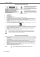
PowerH SERIES IMPORTANT SAFETY INSTRUCTIONS The lightning flash with arrowhead symbol, within an equilateral triangle is intended to alert the user to the presence of uninsulated “dangerous voltage“ within the product’s enclosure that may be of sufficent magnitude to constitute a risk of electric shock to persons.
PowerH SERIES 1 Introduction 1.1 Welcome Dynacord’s new PowerH SERIES power amps herald a new age in power amplifier technology. These highly efficient PowerH amplifiers combine uncompromising audio performance with low weight and highest reliability. Optionally available remote control modules provide the possibility to completely control and monitor the power amps via IRIS-Net™. 1.2 Unpacking and Inspection Carefully open the packaging and take out the power amplifier.
PowerH SERIES 1.4 Features and Description The power amp H2500/H5000 is part of Dynacord’s new PowerH SERIES, which marks a milestone in the design and the production of high-performance power amplifiers. The innovative 3-stage Grounded Bridge Class H Topology with “floating” switching power supply unit offers very high and stable output with extreme high efficiency on an extremely high performance level at minimum weight.
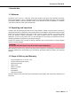
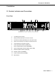
PowerH SERIES 2 Installation 2.1 Controls, Indicators and Connections Front View Illustration 2.
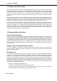
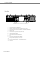
PowerH SERIES Rear View Illustration 2.
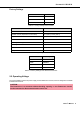
PowerH SERIES Factory Settings Control Setting Mains Switch off Level CH A 0dB Level CH B 0dB Table 2.1: Factory Settings of the Controls Parameter Value Power-On-Delay 0.00 s Breaker Current (dependent on the mains) 16 A (230 V) / 30 A (120 V) Amplifier Name Dynacord H2500 or Dynacord H5000 LCD Contrast 50% LCD Brightness High 90% LCD Brightness Low 40% LCD Time to Dim Autodim off Temperature Unit °C Table 2.
PowerH SERIES During installation, always separate the power amplifier from the mains. Connect the power amplifier only to a mains network, which corresponds to the requirements indicated on the type plate. Illustration 2.3: H2500/H5000 type plate Device Voltage Frequency Power Consumption H2500 100-240 V 50-60 Hz 1000 W H5000 100-240 V 50-60 Hz 1450 W Table 2.
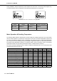
PowerH SERIES H5000 Idle Max. Output Power @ 8 Ω3 Umains in V Imains in A Pmains in W Pout in W Pd in W1 230 0.7 78 - 78 266 230 24.5 4089 2 x 1500 1089 3716 BTU/hr2 230 40.9 7137 2 x 2500 2137 7292 3 230 18.1 2927 2 x 833 1260 4300 3 230 6.2 877 2 x 313 252 860 4 230 9.6 1450 2 x 313 806 2750 45 253 11.6 1944 2 x 378 1188 4053 230 9.2 1368 2 x 250 868 2962 230 37.5 6445 2 x 2100 2245 7660 230 22.7 3760 2 x 1050 1660 5664 230 44.
PowerH SERIES 2.4 Mounting Front Mounting of the Power Amplifier PowerH amplifiers have been designed for installation in a conventional 19-inch rack case. Attach the power amp with its frontal rack mount ears using 4 screws and washers as shown in illustration 2.4. Illustration 2.
PowerH SERIES 2.5 Ventilation As with all Dynacord power amps with fan cooling, the airflow direction is front-to-rear, obviously because there is more cold air outside of the rack case than inside. The power amplifier remains cooler and dissipating the developing waste heat in a specific direction gets easier. In general, setting up or mounting the power amplifier has to be done in a way that fresh air can enter unhindered at the front and exhausted air can exit at the rear.
PowerH SERIES 2.7 Indication of the Operation Mode Two LEDs on the power amp’s front panel indicate the currently selected mode of operation. The PARALLEL-LED lights yellow, when the ROUTING switch is set to PARALLEL. The PARALLEL LED does not light, when the switch is set to DUAL. The BRIDGED LED lights yellow, when the MODE switch is set to BRIDGED. The BRIDGED LED does not light, when the switch is set to NORMAL. 2.
PowerH SERIES MODE The MODE switch on the power amp’s rear panel defines the operation mode of the power amplifier blocks and thus, how a single or more speaker systems have to be connected. NORMAL In two-channel operation (NORMAL), both power amplifier blocks work as independent power amp channels and controlling the amplification of each channel separately is possible. How the power amp’s audio inputs handle input signals depends only on the setting of the ROUTING switch.
PowerH SERIES installer to consider each power amplifier with a gain of 35 dB (or 32 dB) when setting gain structure, independent of the actual maximum output capacity of each individual power amp. Any limiters have to be adjusted to maximum power handling capacity of the loudspeaker components. Audio Cabling Input (XLR / Phoenix) Inputs IN A and IN B are electronically balanced and the SENSITIVITY switch controls input sensitivity.
PowerH SERIES Output (Speakon-type Connectors / Terminals) in Normal Mode With PowerH SERIES amplifiers speaker connection differs depending on the actually selected mode of operation of the power amplifier blocks, i.e. the setting of the MODE switch on the power amp’s rear panel. In NORMAL mode, the loudspeaker systems can be connected in two different ways: using typical Speaker Systems Cabling or Bi-Amp Cabling.
PowerH SERIES Speakon CH A Connection Pin 1+ 1- 2+ 2- Channel Assignment A+ A- B+ B- Table 2.6: Bi-Amp speaker connection in NORMAL operation mode, using only the Speakon A connector Output (Speakon-type Connectors / Terminals) in Bridged Mode Setting the MODE switch on the power amp’s rear panel to BRIDGED lets the power amplifier run in bridged mode operation and speaker connection has to be established using pins 1+ and 2+ of the Speakon socket CH A, see illustration 2.16. Illustration 2.
PowerH SERIES 3 Operation 3.1 Volume Control In DUAL and PARALLEL mode, the level controls CH A and CH B on the power amp’s front panel are used to control the amplification of the corresponding channel. Turning the control to the right increases and turning it to the left decreases the volume. In BRIDGED mode operation, the output volume of the power amp is only controlled by the CH A level control. Any changes in the setting of the CH B level control are ignored.
PowerH SERIES Power Amplifier Menu Navigation Start screen and type designation appear after switching the power amplifier on. The power amp’s status display appears after a few seconds. The top line always shows the name of the power amplifier. An overview of the power amp’s actual condition is provided in lines two and three. Flashing values in line 2 indicate reaching the limit of the permissible operating range.
PowerH SERIES The following illustration shows the structure of the CONFIG menu (and its associated submenus) when opening it from the status display. Menu entries marked with an asterisk * are only available when the remote control module is not installed.
PowerH SERIES Structure of the CONFIG menu Entering the CONFIG menu is possible through pressing the ENTER button while the entry >> CONFIG << is highlighted in the status display. The following provides detailed information about the individual items of the configuration menu. CONFIG/Power-On-Delay: The power amp’s currently set poweron delay is shown. Pressing the ENTER-Taste button opens the Set Power-On-Delay dialog box.
PowerH SERIES CONFIG/Menu Service: The menu entry Menu Service branches to the SERVICE submenu. The entries in the SERVICE menu are explained in detail in paragraph Structure of the CONFIG/SERVICE menu (see page 26). CONFIG/Amplifier Name: Displays the name of the power amplifier. The menu entry only exists when no RCM-26 is installed in the power amplifier. With a remote control module installed, the power amplifier has to be named via IRIS-Net™.
PowerH SERIES CONFIG/EVENT LOG/Counter PROTECT: This item shows how many times one of the protections has been activated. CONFIG/EVENT LOG/Counter AMP MUTE: This menu item shows how often the power amp’s output signal has been muted by one of the protections. CONFIG/EVENT LOG/Counter MAINS FAIL: This menu item shows how many times over- or undervoltage has been recognized at the power amp’s power supply unit.
PowerH SERIES Structure of the CONFIG/DISPLAY SETUP menu CONFIG/DISPLAY SETUP/LCD Contrast: This menu item indicates the currently set contrast of the LC display. Pressing the ENTER button opens the Set LCD Contrast where the user can select a contrast setting in the range of 0 % to 100 % by using the Up/Down buttons. Pressing the ENTER button again stores the selected value for contrast in memory and the CONFIG menu reappears on the display.
PowerH SERIES CONFIG/DISPLAY SETUP/Temperature Unit: The currently selected unit for the indication of temperature values is displayed. Pressing the ENTER button opens the Set Temperature Unit dialog box, which allows selecting °C (Degrees Celsius) or °F (Degrees Fahrenheit) by pressing the Up/Down buttons. Pressing the ENTER button stores the selected unit in memory and the CONFIG menu reappears on the display.
PowerH SERIES CONFIG/SERVICE/Last Log: Shows point in time and type of the last entry in the event history. If service is needed, the code shown here provides relevant detail of what might have caused the malfunction for your Dynacord Service partner. CONFIG/SERVICE/Module Signature: In the event of failure or malfunction, the information shown here provides relevant detail of what might have caused the malfunction for your Dynacord Service partner.
PowerH SERIES Illustration 3.5 shows the structure of the MODULE CONFIG menu of a PowerH SERIES amplifier with an installed RCM-26 remote control module. EXIT Preset CAN-Baudrate Audio-Input Power Illustration 3.5: Structure of the Module Config menu (RCM-26) The following provides detailed information about the individual items of the MODULE CONFIG menu. MODULE CONFIG/Preset: The name of the currently active preset is displayed.
PowerH SERIES MODULE CONFIG/CAN-Baudrate: The currently set CAN baud rate of the RCM-26 is being indicated. Pressing the ENTER button opens the Set CAN-Baudrate dialog box, which by pressing the Up/Down buttons, lets the user select one of the following CAN baud rates: 10kBaud, 20kBaud, 62.5kBaud, 125kBaud, 250kBaud or 500kBaud. Pressing the ENTER button stores the selected baud rate in memory and the display returns to the MODULE CONFIG menu.
PowerH SERIES 3.3 Indications PROTECT Whenever the PROTECT-LED lights yellow, one of the internal protections has been activated. However, a lit PROTECT-LED does not necessarily mean that the signal path gets switched off. The differentiated protections concept of PowerH SERIES power amps results in several protection circuits being activated one after another, which ensures that under normal circumstances the power amplifier will stay in the safe and stabile operating range.
PowerH SERIES IRIS-Net The IRIS-Net-LED lights blue if an IRIS-Net™-compatible remote control module has been installed in the power amp’s extension slot and successful data communication has been established. The IRIS-Net-LED blinks slowly whenever the “Find” function in IRIS-Net™ is being used to locate a power amplifier in the rack. All other LEDs are deactivated during this time. 3.4 Fan Cooling The power amplifier has two fans on the front and one on the rear.
PowerH SERIES 3.6 Protections In case one of the power amp’s internal protections responds during operation, a corresponding message appears on the LC display (or the PROTECT-LED lights) and an entry containing date, time, and protection type is created in the event log. True RMS Mains Voltage and Current Measurement PowerH SERIES amplifiers are consistently informed about the state of the mains network that they are connected to.
PowerH SERIES The power amp’s CPU is acquainted with the temporal progression of the mains current consumption and therefore can simulate the typical behavior of a mains circuit breaker. Nevertheless, pulse peaks allow crest currents that can exceed the nominal value by a multiple.
PowerH SERIES reduced. As soon as the power amp’s temperature returns to a non-critical state, the ATP system imperceptibly switches back to full supply voltage. Thermal Limiter is the second measure that is only activated if, under extreme conditions, Voltage Limitation is not sufficient. The thermal limiter circuit unobtrusively reduces the amplification of the power amplifier.
PowerH SERIES 4 Options Installing one of the optionally available extension modules in the extension slot on the rear panel lets you expand the power amp’s functional range. As an example, the following paragraphs describe all aspects of the RCM-26 Remote Control Module in detail. Please read and follow the instructions provided in the owner’s manuals that you have received together with each extension module. 4.
PowerH SERIES the digital audio input offers a dynamic range of 128 dB. Using the analog audio input offers a dynamic range of 120 dB, which, by the way, is an absolute peak value for digital audio devices. For further details about configuration, control and monitoring of amps with installed RCM-26 modules, please refer to the documentation of the IRIS-Net™ software. Installation Notes 1. Switch the power amp’s power off and pull the mains plug 2. Remove the cover panel from the rear panel (4 screws) 3.
PowerH SERIES Controls and Connections Illustration 4.3: Controls and Connections of the RCM-26 1 AES/EBU-IN A digital AES/EBU input (AES3) is provided in addition to internal analog inputs. The digital input signal has to be connected to the AES/EBU IN connector. The AES/EBU input is a balanced transformer-isolated input. A sampling rate converter translates the input signal to match the internal sampling rate.
PowerH SERIES 3 LOCK-LED The LOCK-LED lights green as soon as the AES/EBU input has been synchronized to the incoming signal and thus proper audio transmission has been established. The LOCK-LED is dimmed with no digital audio signal being present at the input or the internal PLL not having locked on to the incoming signal. The audio signal gets muted when the digital input has been selected.
PowerH SERIES Colour Pin Name 2 CAN_GND 4 CAN_H (+) Blue 5 CAN_L (-) Blue striped 7 MONITOR BUS + Brown striped 8 MONITOR BUS - Brown T568A T568B Green Orange Table 4.2: Overview CAN plug 5 STATUS LED The STATUS-LED is for monitoring the communication on the CAN bus. The LED blinks rhythmically every 3 seconds, when the module’s address is set to “00“, which means that it is disconnected from the CAN bus and software control.
PowerH SERIES HIGH LOW Address 0 0 Stand-alone 0 1...F 1...15 1 0...F 16...31 2 0...F 32...47 3 0...F 48...63 4 0...F 64...79 5 0...F 80...95 6 0...F 96...111 7 0...F 112...127 8 0...F 128...143 9 0...F 144...159 A 0...F 160...175 B 0...F 176...191 C 0...F 192...207 D 0...F 208...223 E 0...F 224...239 F 0...A 240...250 F B...F reserved Table 4.
PowerH SERIES 8 RS-232 Interface The RS-232 interface is for interconnecting the RCM-26 module and multi-media control systems or facility management systems. All parameters can be controlled and queried via RS-232 interface. Communication is realized through the use of ASCII-protocol. Implementation of this protocol is rather simple. Programming notes and a complete protocol description are included in the IRIS-Net™ documentation.
PowerH SERIES Since the CAN interfaces of all EVI Audio appliances are galvanically separated from the rest of the circuitry, network cabling also carries a common ground conductor (CAN_GND) ensuring that all CANinterfaces in the network are connected to a common ground potential. Illustration 4.9: Bus Topology of the CAN bus By using a CAN bus repeater a connection between two independent and self-contained CAN bus systems can be created. Thus, the following can be achieved: • Increase of the max.
PowerH SERIES System Examples The following illustrations show examples of the data-bus wiring for different sizes of CAN-bus networks. Illustration 4.10: System with 5 power amps (with RCM-26) and 1 USB-CAN-Converter. Termination plugs at the USB-CAN-Converter and the RCM-26 of amp 5 Illustration 4.11: System with 2 amp-racks and 1 USB-CAN-Converter.
PowerH SERIES Performance Specifications According to the ISO 11898-2 standard, CAN-bus data transfer cabling has to be carried out using TwistedPair cables with or without shielding providing a characteristic impedance of 120 Ω. Both ends of a CANbus need to be terminated with 120 Ω termination-plugs. The maximum bus-length depends on the actual data transfer rate, the kind of data transfer cable being used, as well as the total number of participants on the bus.
BEDIENUNGSANLEITUNG H 2500 H 5000 PowerH SERIES
PowerH SERIES INHALT Einführung . . . . . . . . . . . . . . . . . . . . . . . . . . . . . . . . . . . . . . . . . . . . . . . . . . . . . . . . . . . . . . . . . Willkommen . . . . . . . . . . . . . . . . . . . . . . . . . . . . . . . . . . . . . . . . . . . . . . . . . . . . . . . . . . . . Auspacken und Inspektion . . . . . . . . . . . . . . . . . . . . . . . . . . . . . . . . . . . . . . . . . . . . . . . . . Lieferumfang und Garantie . . . . . . . . . . . . . . . . . . . . . . . . . . . . . . . . . . .
PowerH SERIES WICHTIGE SICHERHEITSHINWEISE Das Blitzsymbol innerhalb eines gleichseitigen Dreiecks soll den Anwender auf nicht isolierte Leitungen und Kontakte im Geräteinneren hinweisen, an denen hohe Spannungen anliegen, die im Fall einer Berührung zu lebensgefährlichen Stromschlägen führen können. Das Ausrufezeichen innerhalb eines gleichseitigen Dreiecks soll den Anwender auf wichtige Bedienungs- sowie Servicehinweise in der zum Gerät gehörenden Literatur aufmerksam machen. 1. 2. 3. 4. 5. 6. 7. 8. 9.
PowerH SERIES 1 Einführung 1.1 Willkommen Mit den neuen Endstufen der PowerH SERIES von Dynacord beginnt ein neues Zeitalter in der Endstufen-Technologie. Die hocheffiziente PowerH-Endstufe liefert kompromisslose Audioperformance bei geringem Gewicht und höchster Zuverlässigkeit. Durch optionale Remote-ControlModule ist die vollständige Kontrolle und Überwachung der Endstufe über die PC Software IRIS-Net™ möglich. 1.2 Auspacken und Inspektion Öffnen Sie die Verpackung und entnehmen Sie die Endstufe.
PowerH SERIES 1.4 Eigenschaften & Beschreibung Die Endstufe H2500/H5000 gehört zur neuen PowerH SERIES von Dynacord, die einen Meilenstein in Design und Produktion von Hochleistungs-Endstufen darstellt. Die innovative 3-stufige Grounded Bridge Class H Topologie mit „Floating“ Schaltnetzteil bietet eine sehr hohe, stabile Ausgangsleistung bei sehr hohem Wirkungsgrad auf extrem hohem Performance-Niveau und dabei äußerst geringem Gewicht.
PowerH SERIES 2 Installation 2.1 Bedienelemente, Anzeigen und Anschlüsse Frontseite Abbildung 2.1: H2500/H5000 Frontseite 1 2 3 4 5 6 7 8 9 10 11 12 50 LC-Display (mit Bedienelementen) Anzeige Stummschaltung (MUTE) für Kanal A bzw. B Anzeige Schutzschaltung (PROTECT) für Kanal A bzw. B Eingangspegel-Regler (CH A, CH B) für Kanal A bzw. B Pegelanzeige für Kanal A bzw.
PowerH SERIES Rückseite Abbildung 2.
PowerH SERIES Werkseinstellungen Bedienelement Einstellung Netzschalter Aus CH A Level 0dB CH B Level 0dB Tabelle 2.1: Werkseinstellungen Bedienelemente Parameter Wert Power-On-Delay 0.00 s Breaker Current (abhängig vom Leitungsnetz) 16 A (230 V) / 30 A (120 V) Amplifier Name Dynacord H2500 bzw. Dynacord H5000 LCD Contrast 50% LCD Brightness High 90% LCD Brightness Low 40% LCD Time to Dim Autodim off Temperature Unit °C Tabelle 2.
PowerH SERIES Trennen Sie die Endstufe während der Installation immer von der Netzversorgung. Schließen Sie die Endstufe nur an eine geeignete Netzversorgung an, die den auf dem Typenschild angegebenen Anforderungen entspricht. Abbildung 2.3: H2500/H5000 Typenschild Gerät Spannung Netzfrequenz Leistungsaufnahme H2500 100-240 V 50-60 Hz 1000 W H5000 100-240 V 50-60 Hz 1450 W Tabelle 2.
PowerH SERIES H5000 Idle Max. Output Power @ 8 Ω3 Umains in V Imains in A Pmains in W Pout in W Pd in W1 230 0.7 78 - 78 266 230 24.5 4089 2 x 1500 1089 3716 BTU/hr2 230 40.9 7137 2 x 2500 2137 7292 3 230 18.1 2927 2 x 833 1260 4300 3 230 6.2 877 2 x 313 252 860 4 230 9.6 1450 2 x 313 806 2750 45 253 11.6 1944 2 x 378 1188 4053 230 9.2 1368 2 x 250 868 2962 230 37.5 6445 2 x 2100 2245 7660 230 22.7 3760 2 x 1050 1660 5664 230 44.
PowerH SERIES 2.4 Einbau Vordere Befestigung der Endstufe Die PowerH-Endstufe wurde für den Einbau in ein konventionelles 19-Zoll Rack entwickelt. Befestigen Sie die Endstufe an der Vorderseite mit 4 Schrauben und Unterlegscheiben wie in Abbildung 2.4 dargestellt. Abbildung 2.4: Vordere Befestigung der Endstufe bei Rackeinbau Hintere Befestigung Wird das Rack, in dem die Endstufe eingebaut ist, transportiert, muss die Rückseite der Endstufe im Rack befestigt werden.
PowerH SERIES 2.5 Kühlung Bei allen lüftergekühlen Endstufen von Dynacord strömt die Luft von der Frontseite zur Rückseite, da kühle Frischluft eher außerhalb des Racks zur Verfügung steht als innerhalb. Die Endstufe bleibt kühler und die entstehende Abwärme kann gezielter abgeführt werden. Generell ist die Endstufe so aufzustellen oder zu montieren, dass die Luftzufuhr an der Frontseite und die Entlüftung an der Geräterückseite nicht behindert wird. Für den Abbildung 2.
PowerH SERIES 2.7 Anzeige der Betriebsart An der Frontseite der Endstufe zeigen zwei LEDs die momentan gewählte Betriebsart der Endstufe an. Die PARALLEL-LED leuchtet gelb, wenn die Stellung PARALLEL des Schalters ROUTING gewählt ist. Bei Schalterstellung DUAL leuchtet die PARALLEL-LED nicht. Die BRIDGED-LED leuchtet gelb, wenn die Stellung BRIDGED des Schalters MODE gewählt ist. Bei Schalterstellung NORMAL leuchtet die BRIDGED-LED nicht. 2.
PowerH SERIES ACHTUNG: In der Betriebsart PARALLEL kann nur am Eingangskanal A ein Signal eingespeist werden. MODE Der Schalter MODE an der Rückseite der Endstufe bestimmt die Betriebsart der Endstufenblöcke und damit wie ein oder mehrere Lautsprecher angeschlossen werden müssen. NORMAL Im Zweikanalbetrieb (NORMAL) arbeiten beide Endstufenblöcke als unabhängige Endstufenkanäle. Die Verstärkung jedes Kanals kann separat geregelt werden.
PowerH SERIES gewählte Einstellung wird durch grünes Aufleuchten der entsprechend beschrifteten LED an der Frontblende angezeigt. HINWEIS: Bei Verwendung eines Remote-Control-Moduls ist der Sensitivity/Gain-Schalter an der Endstufe ohne Funktion. Es wird automatisch die Einstellung 35dB festgelegt. Eine Eingangsempfindlichkeit von 0dBu bedeutet, dass bei einem Eingangssignal von 0 dBu (0.775 Vrms) am Endstufenausgang die Nennleistung (Rated Output Power) abgegeben wird.
PowerH SERIES Netzzuführungen, HF-Steuerleitungen usw. ist jedoch eine symmetrische Verkabelung immer zu bevorzugen. 2, HOT JUMPER FROM COLD TO SHIELD HOT, + 3, COLD JUMPER FROM COLD TO SHIELD SHIELD Abbildung 2.11: Unsymmetrische Beschaltung des Eingangs Zusätzlich zu den Eingängen steht für jeden Kanal jeweils eine parallel geschaltete XLR-Buchse (OUT A bzw. OUT B) zur Verfügung. Über diese kann das Audiosignal komfortabel zu anderen Geräten weitergeführt werden (Daisy-Chain).
PowerH SERIES Speakon CH B Speakon CH A 1+ 1- Anschluss 1+ 1- B+ B- Belegung A+ A- Tabelle 2.5: Lautsprecheranschluss in Betriebsart NORMAL an Speakon A und B Neben den Speakon-Buchsen stehen für den Anschluss von Lautsprechern auch Anschlussklemmen zur Verfügung. In der Betriebsart NORMAL werden die Lautsprecher entsprechend folgender Abbildung angeschlossen. Abbildung 2.
PowerH SERIES Ausgang (Speakon / Anschlussklemmen) im Bridged Mode Läuft die Endstufe durch Wahl der Schalterstellung BRIDGED des Schalters MODE an der Rückseite im Brückenbetrieb, ist der Lautsprecher an der Speakon-Buchse CH A an den Anschlüssen 1+ und 2+ zu betreiben, siehe Abbildung 2.15. Abbildung 2.16: Lautsprecheranschluss in Betriebsart BRIDGED an Speakon A Speakon CH A Anschluss 1+ 2+ Belegung Bridged+ Bridged- Tabelle 2.
PowerH SERIES 3 Betrieb 3.1 Volume Control In den Betriebsarten DUAL und PARALLEL regeln die Levelsteller CH A bzw. CH B an der Frontseite der Endstufe die Verstärkung des jeweiligen Kanals. Drehung nach rechts erhöht die Lautstärke, Drehung nach links verringert die Lautstärke. In der Betriebsart BRIDGED regelt nur der Drehknopf CH A die Lautstärke der Endstufe. Änderungen der Einstellung des Drehknopfs CH B werden ignoriert.
PowerH SERIES Menüführung Endstufe Nach dem Einschalten der Endstufe wird der Startbildschirm mit der Typenbezeichnung der Endstufe angezeigt. Nach einigen Sekunden wird die Statusanzeige der Endstufe dargestellt. In der obersten Zeile wird immer die Bezeichnung der Endstufe angezeigt. Die zweite und dritte Zeile liefert einen Überblick über den aktuellen Zustand der Endstufe. Blinkende Werte in Zeile 2 weisen auf das Erreichen des jeweils zulässigen Betriebsbereiches hin. Ist in die Endstufe z.B.
PowerH SERIES Folgende Abbildung stellt die Struktur des Menüs CONFIG (und der zugehörigen Untermenüs) ausgehend von der Statusanzeige dar. Mit * markierte Menüeinträge sind nur dann verfügbar, wenn kein Remote Control Modul eingebaut ist.
PowerH SERIES Menüstruktur CONFIG Das Konfigurationsmenü CONFIG erreicht man durch Drücken der ENTER-Taste bei Anzeige des Eintrags >> CONFIG << im Statusdisplay. Nachfolgend sind die einzelnen Einträge des Konfigurationsmenüs erläutert. CONFIG.Power-On-Delay: Es wird die momentan eingestellte Einschaltverzögerung der Endstufe angezeigt. Durch Drücken der ENTER-Taste gelangt man in den Dialog Set Power-On-Delay.
PowerH SERIES CONFIG.Menu Display: Der Menüeintrag Menu Display führt in das Untermenü DISPLAY SETUP. Die einzelnen Einträge des Menüs DISPLAY SETUP sind im Abschnitt Menüstruktur CONFIG.DISPLAY SETUP (siehe Seite 69) erläutert. CONFIG.Menu Service: Der Menüeintrag Menu Service führt in das Untermenü SERVICE. Die einzelnen Einträge des Menüs SERVICE sind im Abschnitt Menüstruktur CONFIG.SERVICE (siehe Seite 70) erläutert. CONFIG.Amplifier Name: Zeigt die Bezeichnung der Endstufe an.
PowerH SERIES Menüstruktur CONFIG.EVENT LOG CONFIG.EVENT LOG.Counter POWER UP: Es wird die Anzahl der Betätigungen des Netzschalters an der Frontseite angezeigt. CONFIG.EVENT LOG.Counter AMP ON: Es wird die Anzahl der Aktivierungen der Endstufe, sowohl aus dem Zustand Aus als auch aus dem Zustand Standby, angezeigt. CONFIG.EVENT LOG.Counter PROTECT: Es wird die Anzahl des Ansprechens einer Schutzschaltung angezeigt. CONFIG.EVENT LOG.
PowerH SERIES CONFIG.EVENT LOG.Reset Event Log: Das Event Log der Endstufe kann komplett zurückgesetzt werden. Durch das Rücksetzen werden alle Zähler auf Null gesetzt und die Ereignisliste wird gelöscht. Durch Drücken der ENTER-Taste gelangt man zu einer Sicherheitsabfrage. In der Sicherheitsabfrage kann durch Drücken der Up/Down-Tasten zwischen YES und NO gewählt werden.
PowerH SERIES CONFIG.DISPLAY SETUP.LCD Time to Dim: Es wird die momentan eingestellte Beleuchtungsdauer des Displays angezeigt. Nach Ablauf dieser Zeitdauer wird die Displaybeleuchtung zurückgedimmt. Durch Drücken der ENTER-Taste gelangt man in den Dialog Set LCD Time to Dim. Im Dialog Set Time to Dim kann durch Drücken der Up/DownTasten die Zeitdauer bis zum Dimmvorgang der Displaybeleuchtung eingestellt werden. Einerseits kann die Zeitdauer auf 4, 8, 16, 32 bzw.
PowerH SERIES Die durch den Rücksetzvorgang betroffenen Parameter sind in folgender Tabelle zusammengefasst: Parameter Wert Power-On-Delay 0.00 s Breaker Current (abhängig von Versorgungsspannung) 16 A (230 V) / 30 A (120 V) Amplifier Name Dynacord H2500 bzw. Dynacord H5000 LCD Contrast 50% LCD Brightness High 90% LCD Brightness Low 40% LCD Time to Dim Autodim off Temperature Unit °C Tabelle 3.3: Werkseinstellungen LC-Display CONFIG.SERVICE.
PowerH SERIES Menüstruktur MODULE CONFIG Alle Einstellmöglichkeiten am Remote-Control-Modul RCM-26 über das LC-Display der Endstufe sind in einem eigenen Menü MODULE CONFIG zusammengefasst. Dieses Menü ist während des Betriebs der Endstufe nicht zugänglich. Der Zugang zu diesem Menü ist nur von der ausgeschalteten Endstufe aus möglich. Folgende Schritte öffnen des Menü MODULE CONFIG: 1.
PowerH SERIES MODULE CONFIG.Preset: Es wird die Bezeichnung des momentan aktiven Presets angezeigt. Durch Drücken der ENTERTaste gelangt man in den Dialog Load Preset. Im Dialog Load Preset kann durch Drücken der Up/DownTasten zwischen den verschiedenen Presets gewählt werden. Drücken der ENTER-Taste führt zu einer Sicherheitsabfrage, ob das Preset wirklich geladen werden soll. In diesem Dialog kann durch Drücken der Up/Down-Tasten zwischen YES und NO gewählt werden.
PowerH SERIES MODULE CONFIG.Power: Es wird der Zustand der Endstufe nach Betätigung des Netzschalters angezeigt. Falls die Endstufe über IRIS-Net™ in den Standby-Modus geschaltet und über den Netzschalter ausgeschaltet wurde, wird der Standby-Zustand beim nächsten Einschalten der Endstufe über den Netzschalter angenommen. Über diesen Menüpunkt kann eine Endstufe im Standby-Modus auch ohne IRIS-Net™ wieder hochgefahren werden. Durch Drücken der ENTER-Taste gelangt man in den Dialog Set Power.
PowerH SERIES POWER Die POWER-LED leuchtet grün auf, wenn die Endstufe eingeschaltet ist. Falls die POWER-LED trotz eingeschaltetem Gerät nicht leuchtet, ist das Gerät entweder nicht mit dem Stromnetz verbunden, die Primärsicherung defekt, oder die Endstufe befindet sich im Standby-Modus (STANDBY-LED leuchtet gelb). Die POWER-LED blinkt, wenn die Spannung am Eingang MAINS IN entweder zu hoch (Überspannung) oder zu niedrig (Unterspannung) ist. In diesem Fall lässt sich die Endstufe nicht einschalten.
PowerH SERIES Bei Betrieb der Endstufe in einem Umfeld mit besonders hoher Staubbelastung wird der Einbau von Luftfiltern empfohlen. Hierbei ist jedoch eine regelmäßige Überprüfung der Filter auf Staubablagerungen und, falls notwendig, Reinigung bzw. Austausch der Filter dringend erforderlich. Hierdurch wird einer unnötigen thermischen Belastung und dem Ansprechen der Thermal Protection vorgebeugt. 3.
PowerH SERIES die beiden Betriebsarten 120 V und 220-240 V die zulässigen Wertebereiche und Voreinstellungen zusammen. Betriebsart Minimum Maximum Werkseinstellung 120 V 6A 40 A 30 A 220-240 V 6A 30 A 16 A Tabelle 3.4: Mains Circuit Breaker Protection Die CPU der Endstufe kennt den zeitlichen Verlauf des aufgenommenen Netzstromes und kann damit das Verhalten eines typischen Netzsicherungsautomaten simulieren.
PowerH SERIES Advanced Thermal Protection Mit den Endstufen der PowerH SERIES wird das neue System Advanced Thermal Protection (ATP) eingeführt. Dieses neue System unterscheidet sich richtungsweisend von traditionellen thermischen Schutzmechanismen. Diese schalten relativ frühzeitig den gesamten Signalpfad ab, sobald die Lüfter nicht mehr in der Lage sind, die Verlustwäre aus der Endstufe abzuführen. Das Abschalten des Signalpfades ist im ATP-System erst der letzte von drei aufeinander folgenden Schritten.
PowerH SERIES Hochttonlautsprechern ist es, wenn das Signal noch im hörbaren Bereich bzw. knapp über der Hörgrenze liegt. Konventionelle HF-Schutzschaltungen reagieren in diesem Bereich nicht empfindlich genug, da sie primär darauf ausgelegt sind, Fehler der Endstufe selbst zu erkennen. Endstufen der PowerH SERIES verfügen daher zusätzlich zum konventionellen HF-Schutz über einen HF-Limiter.
PowerH SERIES 4 Optionen Durch den Einbau eines optionalen Zusatzmoduls in den Erweiterungssteckplatz an der Rückseite kann der Funktionsumfang der Endstufe erhöht werden. Als Beispiel wird im folgenden das RCM-26 Remote Control Modul aufgeführt. Bitte beachten Sie bei allen Zusatzmodulen die jeweils mitgelieferte Bedienungsanleitung. 4.1 RCM-26 Systembeschreibung Das RCM-26 Remote Control Modul ist ein zweikanaliges Digital-Controller Modul für Live Sound, PA und Festinstallation.
PowerH SERIES Der analoge Audioeingang erreicht eine Dynamik von 120 dB, ebenfalls ein absoluter Spitzenwert für digitale Audiogeräte. Sämtliche Details zur Konfiguration, Steuerung und Überwachung von Endstufen mit eingebauten RCM-26 Modulen sind in der Dokumentation der Software IRIS-Net™ enthalten. Installationshinweise 1. Endstufe ausschalten und Netzstecker abziehen 2. Leerblende an Rückwand der Endstufe abschrauben (4 Schrauben) 3.
PowerH SERIES Bedienelemente und Anschlüsse Abbildung 4.3: Bedienelemente und Anschlüsse des RCM-26 1 AES/EBU-IN Neben den internen Analogeingängen steht ein digitaler AES/EBU Eingang (AES3) zur Verfügung. Das digitale Eingangssignal wird an die Buchse AES/EBU IN angeschlossen. Es handelt sich um einen symmetrischen Eingang mit Übertrager zur galvanischen Isolierung. Über einen Sample-Rate-Converter wird das Signal an die interne Abtastrate angepasst.
PowerH SERIES 3 LOCK-LED Die LOCK-LED leuchtet grün, wenn der AES/EBU-Eingang auf das empfangene Signal synchronisiert ist und die Audioübertragung in Ordnung ist. Wenn die LOCK-LED nicht leuchtet, liegt entweder kein digitales Audiosignal an, oder die interne PLL ist nicht auf das ankommende Signal eingrastet. Falls der Digital-Eingang gewählt ist, wird das Audiosignal in diesem Fall stumm geschaltet.
PowerH SERIES Abbildung 4.7: Belegung des CAN-Steckers Kabelfarbe nach Pin Name 2 CAN_GND 4 CAN_H (+) Blau 5 CAN_L (-) Blau gestreift 7 MONITOR BUS + Braun gestreift 8 MONITOR BUS - Braun T568A T568B Grün Orange Tabelle 4.2: Übersicht CAN-Stecker 5 STATUS LED Die STATUS-LED dient zur Kontrolle der Kommunikation am CAN-Bus. Die LED blinkt regelmäßig alle 3 Sekunden kurz auf, wenn das Modul mit 00 adressiert und damit softwaremäßig vom CAN-Bus abgekoppelt ist.
PowerH SERIES HIGH LOW Adresse 0 0 Stand-alone 0 1...F 1...15 1 0...F 16...31 2 0...F 32...47 3 0...F 48...63 4 0...F 64...79 5 0...F 80...95 6 0...F 96...111 7 0...F 112...127 8 0...F 128...143 9 0...F 144...159 A 0...F 160...175 B 0...F 176...191 C 0...F 192...207 D 0...F 208...223 E 0...F 224...239 F 0...A 240...250 F B...F reserviert Tabelle 4.
PowerH SERIES 8 RS-232 Schnittstelle Die RS-232 Schnittstelle dient der Verbindung des RCM-26 mit Mediensteuerungssystemen bzw. Gebäudemanagementsystemen. Über RS-232 können sämtliche Parameter gesteuert und abgefragt werden. Die Kommunikation erfolgt über ein einfach zu implementierendes ASCII-Protokoll. Programmierhinweise und eine vollständige Protokollbeschreibung sind in der IRIS-Net™-Dokumentation enthalten.
PowerH SERIES Da die CAN-Schnittstelle in allen EVI Audio Geräten galvanisch getrennt von den übrigen Schaltungsteilen aufgebaut ist, wird auch eine gemeinsame Masseleitung (CAN_GND) in der Netzwerkverkabelung mitgeführt (siehe folgende Abbildung). Damit ist sichergestellt, dass alle CAN-Schnittstellen im Netzwerk auf einem gemeinsamen Potential liegen. Abbildung 4.
PowerH SERIES Systembeispiele Die folgenden beiden Abbildungen zeigen Beispiele von Systemverdrahtungen eines Remote-ControlNetzwerks. Zur Verbindung des Remote-Control-Netzwerks mit einem PC wird jeweils ein USB-CANConverter verwendet. Abbildung 4.10: 5 Remote-Amplifier (mit RCM-26) und ein USB-CAN-Converter am Bus-Anfang. Abschluss-Stecker am USB-CAN-Converter und am RCM-26 des Remote-Amplifier 5 Abbildung 4.11: System mit 2 Racks und einem USB-CAN-Converter.
PowerH SERIES Leitungsspezifikation Gemäß dem ISO 11898-2 Standard sollten für den CAN-Bus als Datenübertragungskabel vorzugsweise Twisted-Pair-Leitungen, geschirmt oder ungeschirmt, mit einem Wellenwiderstand von 120 Ω zum Einsatz kommen. Als Leitungsabschluss muss an beiden Enden ein Abschlusswiderstand von 120 Ω vorgesehen werden. Die maximale Buslänge ist abhängig von der Datenübertragungsrate, von der Art des Datenübertragungskabels sowie von der Anzahl der Bus-Teilnehmer.
PowerH SERIES 90 Bedienungsanleitung
MODE D’EMPLOI H 2500 H 5000 PowerH SERIES
PowerH SERIES MATIÈRES Introduction . . . . . . . . . . . . . . . . . . . . . . . . . . . . . . . . . . . . . . . . . . . . . . . . . . . . . . . . . . . . . . . . . Bienvenue . . . . . . . . . . . . . . . . . . . . . . . . . . . . . . . . . . . . . . . . . . . . . . . . . . . . . . . . . . . . . Déballage et inspection . . . . . . . . . . . . . . . . . . . . . . . . . . . . . . . . . . . . . . . . . . . . . . . . . . . Détails de la livraison et garantie . . . . . . . . . . . . . . . . . . . . . . . . . .
PowerH SERIES IMPORTANT INFORMATIONS DE SÉCURITÉ Le symbole „éclair“ à l’intérieur d’un triangle signale à l’utilisateur la présence dans l’appareil de câbles et de contacts qui ne sont pas isolés, dans lesquels circule un courant électrique à haute tension, et qu’on ne doit en aucun cas toucher afin d’éviter de recevoir une décharge électrique qui pourrait être mortelle.
PowerH SERIES 1 Introduction 1.1 Bienvenue Les nouveaux amplificateurs de puissance PowerH SERIES Dynacord marquent une ère nouvelle dans la technologie des amplis de puissance. Les amplificateurs superbement efficaces PowerH combinent des performances audio sans compromis, un poids léger et une fiabilité exceptionnelle. Des modules de télécommande optionnels leur donnent la possibilité d’être totalement contrôlés et monitorés via IRIS-Net™. 1.
PowerH SERIES efficacité à un fort niveau de performance et pour un poids minimum. Les amplis PowerH sont idéals pour les grandes tournées, les concerts de qualité et les applications sonores professionnelles. En plus des protections habituelles, cette nouvelle conception emploie pour la première fois le système ATP multi-étage (Advanced Thermal Protection), qui dans la plupart des cas évite l’extinction de l’amplificateur de puissance lorsque la température excède un seuil critique.
PowerH SERIES 2 Installation 2.1 Commandes, témoins et branchements Face avant Illustration 2.
PowerH SERIES Arrière Illustration 2.
PowerH SERIES Réglages d’usine Contrôle Réglage Interrupteur secteur off Niveau CH A 0dB Niveau CH B 0dB Tableau 2.1 : Réglages d’usine des commandes Paramètre Valeur Délai de mise sous tension 0.00 s Courant de coupure (en fonction du secteur) 16 A (230 V) / 30 A (120 V) Nom de l’amplificateur Dynacord H2500 ou Dynacord H5000 Contraste du LCD 50% Brillance forte du LCD 90% Brillance faible du LCD 40% Extinction du LCD Autodim off Unité de Température °C Tableau 2.
PowerH SERIES Pendant l’installation, toujours débrancher l’amplificateur de puissance du secteur. Connecter l’amplificateur de puissance uniquement sur le réseau électrique principal, correspondant aux spécifications indiquées sur la plaque d’identification. Illustration 2.3 : Plaque d’identité du H2500/H5000 Appareil Tension Fréquence Consommation H2500 100-240 V 50-60 Hz 1000 W H5000 100-240 V 50-60 Hz 1450 W Tableau 2.
PowerH SERIES H5000 Umains in V Au repos Puissance de sortie Max. @ 8 Ω3 Imains in A Pmains in W Pout in W Pd in W1 BTU/hr2 230 0.7 78 - 78 266 230 24.5 4089 2 x 1500 1089 3716 2 x 2500 2137 7292 230 40.9 7137 3 230 18.1 2927 2 x 833 1260 4300 3 230 6.2 877 2 x 313 252 860 4 230 9.6 1450 2 x 313 806 2750 45 253 11.6 1944 2 x 378 1188 4053 230 9.2 1368 2 x 250 868 2962 230 37.5 6445 2 x 2100 2245 7660 230 22.
PowerH SERIES 2.4 Montage Montage par l’avant de l’amplificateur de puissance Les amplificateurs PowerH ont été conçus pour être installés dans un rack 19 pouces conventionnel. Fixez l’ampli de puissance par ses montants avant à l’aide des 4 vis et rondelles comme indiqué sur l’illustration 2.4. Illustration 2.
PowerH SERIES 2.5 Ventilation Comme tous les amplis de puissance Dynacord refroidis par ventilateur, la direction du flux d’air va de l’avant vers l’arrière, puisqu’il y a davantage d’air frais en dehors du rack qu’à l’intérieur. Il est plus facile de maintenir l’amplificateur de puissance plus froid en dissipant la chaleur produite dans une direction spécifique.
PowerH SERIES 2.6 Mise à la masse Le commutateur de masse Ground-Lift permet d'éliminer les bruits dus à une boucle de masse. Si l'amplificateur de puissance fonctionne avec d'autres équipements installés dans une armoire de rack, il convient de régler ce commutateur en position GROUNDED. Si l'amplificateur de puissance fonctionne avec d'autres appareils ayant des potentiels de masse différents, réglez ce commutateur en position UNGROUNDED. 2.
PowerH SERIES mode à choisir, chaque fois que le même signal d’entrée arrive sur plusieurs canaux de l’ampli de puissance dans une grande configuration, par exemple pour attaquer une ligne de caissons de basse. Illustration 2.8 : Signal audio appliqué au connecteur d’entrée A en mode PARALLEL ATTENTION : En mode PARALLEL, le signal d’entrée doit alimenter uniquement le canal A.
PowerH SERIES ATTENTION : Il ne faut pas faire fonctionner l'ampli de puissance en Mode Bridged si la charge connectée tombe en-dessous de 4 ohms. Des tensions extrêmement élevées peuvent être présentes en sortie. Les haut-parleurs connectés doivent pouvoir supporter de telles tensions. Veuillez vérifier que les caractéristiques électriques mentionnées dans la documentation qui accompagne vos haut-parleurs correspondent à celles de l'amplificateur de puissance.
PowerH SERIES Chaque fois que c’est possible, il est préférable d’utiliser un signal audio symétrisé pour alimenter l’entrée de l’amplificateur de puissance. Des branchements non symétrisés ne seront possibles qu’avec des câbles très courts et s’il n’y a pas d’interférences entre les signaux passant par l’amplificateur de puissance. De ce cas, il sera obligatoire de ponter la tresse (blindage) et la fiche de l’entrée inverse du connecteur. Sinon, une chute de niveau de 6 dB pourrait se produire.
PowerH SERIES Speakon CH B Speakon CH A 1+ 1- Connecteur 1+ 1- B+ B- Câblage A+ A- Tableau 2.5 : Branchement des HP en mode de fonctionnement NORMAL, à l’aide des connecteurs Speakon A et B À côté des prises de type Speakon, des bornes conventionnelles pour le branchement des haut-parleurs sont également fournies. L’illustration suivante montre comment connecter les haut-parleurs en mode de fonctionnement NORMAL. Illustration 2.
PowerH SERIES Sortie (Connecteurs / Bornes de type Speakon) en mode Bridged (ponté) Le fait de régler le sélecteur de MODE situé à l’arrière de l’ampli de puissance sur BRIDGED permet à l’amplificateur de puissance de fonctionner en mode «ponté» ; le branchement des haut-parleurs doit être effectué sur les fiches 1+ et 2+ de la prise Speakon CH A, voir l’illustration 2.16. Illustration 2.
PowerH SERIES 3 Fonctionnement 3.1 Contrôle du volume En modes DUAL et PARALLEL, les contrôles de volume CH A et CH B situés sur la face avant de l’ampli de puissance servent à contrôler l’amplification du canal correspondant. Les faire tourner vers la droite augmente le volume et vers la gauche le diminue. En mode BRIDGED, le volume de sortie de l’ampli de puissance est uniquement contrôlé à l’aide du potentiomètre CH A. Tout changement de réglage du contrôle de volume CH B seront ignorés.
PowerH SERIES Navigation dans les menus de l’amplificateur de puissance L’écran de départ mentionnant le nom de l’ampli apparaît après la mise sous tension de l’amplificateur de puissance. L’écran mentionnant l’état de l’ampli de puissance apparaît après quelques secondes. La ligne du haut indique toujours le nom de l’amplificateur de puissance. Un aperçu des conditions actuelles de l’ampli de puissance est donné sur les lignes deux et trois.
PowerH SERIES L’illustration suivante montre la structure du menu CONFIG (et des sous-menus associés) lorsqu’il est ouvert à partir de l’écran d’état. Les options de menu marquées d’un astérisque * ne sont disponibles que si le module de télécommande a été installé.
PowerH SERIES Structure du menu CONFIG Vous accédez au menu CONFIG en pressant la touche ENTER lorsque l’option >> CONFIG << est surlignée dans l’écran d’état. Voici des informations détaillées sur chacune des options du menu configuration. CONFIG/Power-On-Delay: Affichage du délai de mise sous tension actuel de l’ampli de puissance. Presser la touche ENTERouvrira le dialogue de réglage Set Power-On-Delay .
PowerH SERIES CONFIG/Menu Display: L’option de menu Menu Display vous amène au sous-menu DISPLAY SETUP. Chacune des options du menu DISPLAY SETUP est décrite en détails dans le paragraphe Structure du menu CONFIG/DISPLAY SETUP (voir page 115). CONFIG/Menu Service: L’option de menu Menu Service vous amène au sous-menu SERVICE. Les options du menu SERVICE sont décrites en détails dans le paragraphe Structure du menu CONFIG/SERVICE (voir page 116).
PowerH SERIES Structure du menu CONFIG/EVENT LOG CONFIG/EVENT LOG/Counter POWER UP: Cette option de menu montre combien de fois l’interrupteur secteur de la face avant a été utilisé. CONFIG/EVENT LOG/Counter AMP ON: Cette option de menu montre combien de fois l’amplificateur de puissance a été activé à partir de l’état OFF ou STANDBY. CONFIG/EVENT LOG/Counter PROTECT: Cette option de menu montre combien de fois une des protections a été activée.
PowerH SERIES CONFIG/EVENT LOG/Reset Event Log: L’utilisateur peut totalement réinitialiser le journal Event Log de l’amplificateur de puissance grâce à cette option de menu.Tous les compteurs seront remis à zéro et le journal sera effacé. Pressez la touche ENTER ouvre un dialogue de sécurité permettant de choisir entre YES (Oui) ou NO (Non) en pressant les touches Haut/Bas. Si vous répondez YES, le fait de presser la touche ENTER réinitialisera le journal Event Log.
PowerH SERIES CONFIG/DISPLAY SETUP/LCD Time to Dim: Représente la durée pendant laquelle l’écran brille au maximum en fonction de la brillance choisie. A la fin de cette période, la brillance de l’écran diminue. Pressez la touche ENTER pour ouvrir le dialogue Set LCD Time to Dim, dans lequel vous pouvez spécifier la durée après laquelle la brillance de l’écran va diminuer en pressant les touches Haut/Bas. Cette durée peut être réglée sur 4, 8, 16, 32 ou 64 minutes.
PowerH SERIES Le tableau suivant dresse la liste de tous les paramètres concernés par une réinitialisation: Paramètre Valeur Power-On-Delay 0.00 s Breaker Current (dépend de la tension d’alimentation) 16 A (230 V) / 30 A (120 V) Nom de l’amplificateur Dynacord H2500 ou Dynacord H5000 LCD Contrast 50 % LCD Brightness High 90 % LCD Brightness Low 40 % LCD Time to Dim Autodim off Temperature Unit °C Tableau 3.
PowerH SERIES Structure du menu MODULE CONFIG Le menu MODULE CONFIG donne accès au réglage du module de télécommande RCM-26, qui sont disponibles depuis l’écran LCD de l’amplificateur de puissance. Ce menu n’est pas accessible lorsque l’amplificateur de puissance fonctionne. L’accès à ce menu n’est possible que lorsque l’ampli de puissance est hors tension. Suivez ces étapes pour ouvrir le menu MODULE CONFIG : 1.
PowerH SERIES MODULE CONFIG/Preset: Affiche le nom du préréglage actuellement actif. Pressez la touche ENTER pour ouvrir le dialogue Load Preset, permettant de sélectionner un préréglage (preset) à l’aide des touches Haut/Bas. Pressez la touche ENTER ouvre un dialogue de sécurité permettant de choisir entre YES (Oui) ou NO (Non) en pressant les touches Haut/Bas. Si vous répondez YES, le fait de presser la touche ENTER chargera le préréglage sélectionné et l’écran reviendra au menu MODULE CONFIG.
PowerH SERIES MODULE CONFIG/Power: L’état de fonctionnement de l’ampli de puissance qui sera utilisé après appui sur l’interrupteur secteur est affiché ici. Si le mode standby a été activé via IRIS-Net™ et que l’amplificateur de puissance a été mis hors tension à l’aide de l’interrupteur secteur, l’ampli de puissance redémarrera automatiquement en mode standby à la prochaine mise sous tension à l’aide de l’interrupteur secteur.
PowerH SERIES POWER Le témoin à LED POWER s’allume en vert lorsque l’amplificateur de puissance est sous tension. Si ce témoin ne s’allume pas, alors que l’amplificateur a été mis sous tension, ceci indique que l’ampli de puissance n’est pas raccordé au secteur, que le fusible principal a sauté, ou que l’amplificateur est en mode standby (témoin STANDBY allumé en jaune).
PowerH SERIES 3.6 Protections Si une des protections internes de l’ampli de puissance s’active en cours de fonctionnement, un message correspondant apparaît sur l’écran LCD (ou le témoin à LED PROTECT s’allume) et un article contenant la date, l’heure et le type de protection est créé dans l’historique «Event Log». Tension secteur RMS réelle et mesure du courant Les amplificateurs PowerH SERIES sont constamment informés de l’état du réseau électrique auquel ils sont reliés.
PowerH SERIES Le processeur de l’ampli de puissance calcule la progression dans le temps de la consommation électrique et peut donc simuler le comportement typique d’un coupe-circuit. Les pics d’impulsion provoquant des crêtes de courants ne peuvent jamais excéder un certain multiple de la valeur nominale.
PowerH SERIES le développement de chaleur est vraiment réduit. Dès que la température de l’ampli de puissance revient à un état non-critique, le système ATP retourne imperceptiblement à une tension d’alimentation normale. La limitation thermique est la seconde mesure qui est activée si, dans des conditions extrêmes, la limitation de la tension n’a pas été suffisante. Le circuit de limitation thermique réduit alors discrètement l’amplification.
PowerH SERIES 4 Options En installant un des modules d’extension disponibles en option dans le slot d’extension situé à l’arrière vous pourrez étendre les fonctionnalités de votre ampli de puissance. Par exemple, les paragraphes suivants décrivent en détails tous les aspects du Module de Télécommande RCM-26. Veuillez lire et suivre les instructions mentionnées dans le mode d’emploi que vous avez reçu avec chacun des modules d’extension. 4.
PowerH SERIES AES3 (AES/EBU) équipée d’un connecteur de type XLR sont fournies. L’entrée audio numérique offre une dynamique de 128 dB. L’entrée audio analogique possède quant à elle une dynamique de 120 dB, ce qui permet de brancher tous les appareils audio numériques avec un maximum de rendement. Pour les détails concernant la configuration, le contrôle et le monitoring des amplis équipés de modules RCM-26, veuillez vous reporter à la documentation du logiciel IRIS-Net™. Remarques sur l’installation 1.
PowerH SERIES Commandes et connexions Illustration 4.3: Commandes et connexions RCM-26 1 AES/EBU-IN Une entrée numérique AES/EBU (AES3) est fournie en plus des entrées analogiques internes. Le signal d’entrée numérique doit être relié au connecteur AES/EBU IN. L’entrée AES/EBU est isolée par un transformateur symétrisé. Un convertisseur de fréquence d’échantillonnage convertit le signal d’entrée pour qu’il corresponde à la fréquence d’échantillonnage interne.
PowerH SERIES 3 Témoin LOCK Le témoin à LED “LOCK” s’allume en vert dès que l’entrée AES/EBU s’est synchronisée au signal reçu et qu’une transmission audio est établie. Le témoin LOCK s’éteint quand aucun signal audio numérique n’est présent à l’entrée ou lorsque le PLL interne n’est pas verrouillé sur le signal reçu. Le signal audio est coupé lorsque l’entrée numérique est sélectionnée.
PowerH SERIES Illustration 4.7: Câblage de la prise CAN Fiche Non Couleur T568A T568B Vert Orange 2 CAN_GND 4 CAN_H (+) Bleu 5 CAN_L (-) Rayé bleu 7 MONITOR BUS + Rayé brun 8 MONITOR BUS - Brun Tableau 4.2: Vue d’ensemble de la prise CAN 5 Témoin STATUS Le témoin à LED “STATUS” sert à surveiller la communication sur le bus CAN.
PowerH SERIES HIGH LOW Addresse 0 0 Indépendant 0 1...F 1...15 1 0...F 16...31 2 0...F 32...47 3 0...F 48...63 4 0...F 64...79 5 0...F 80...95 6 0...F 96...111 7 0...F 112...127 8 0...F 128...143 9 0...F 144...159 A 0...F 160...175 B 0...F 176...191 C 0...F 192...207 D 0...F 208...223 E 0...F 224...239 F 0...A 240...250 F B...F réservé Table 4.
PowerH SERIES 8 Interface RS-232 L’interface RS-232 sert à l’interconnexion du module RCM-26 et de systèmes de contrôle multi-media ou de gestion divers. Tous les paramètres peuvent être contrôlés et requis via l’interface RS-232. La communication s’effectue au moyen du protocole ASCII. L’implémentation de ce protocole est assez simple. Des notes de programmation et une description complète du protocole se trouvent dans la documentation IRIS-Net™.
PowerH SERIES Illustration 4.9: Topologie du bus CAN En employant un répétiteur de bus CAN une connexion entre deux systèmes de bus CAN indépendants peut être créée. Il est alors possible de: • Augmenter le nombre maximum de membres Un maximum de 100 appareils peuvent être connectés à un même bus CAN. Ce nombre peut être augmenté jusqu'à 250 en reliant plusieurs systèmes de bus CAN. Cette limitation à exactement 250 appareils est due au schéma d'adressage utilisé par le bus CAN.
PowerH SERIES Exemples de systèmes Les illustrations suivantes montrent des exemples de câblage de type bus de données pour différentes tailles de réseau CAN. Illustration 4.10: Système avec 5 amplis de puissance et un UCC-1 au début de la chaîne (bus). Bouchons de terminaison sur le UCC-1 (première unité du bus) et sur l'ampli 5 (dernière unité du bus). Illustration 4.11: Système avec avec 2 amplis en rack et un UCC-1 au milieu.
PowerH SERIES Caractéristiques des Performances Selon le standard ISO 11898-2, le câblage pour transfert de données du bus CAN doit être réalisé avec des câbles à paire torsadée avec ou sans blindage ayant une caractéristique d'impédance de 120 Ω. Les deux extrêmités du bus CAN doivent être terminées par des bouchons de terminaison de 120 Ω. La longueur maximum du bus dépend de la vitesse de transfert réelle, du type de câble employé pour ce transfert, ainsi que du nombre total de participants sur le bus.
PowerH SERIES Specifications/Technische Daten H2500 Amplifier at rated conditions, both channels driven, 8 Ω load, unless otherwise specified. 2Ω 4Ω 8Ω 2000 W 1450 W 850 W - 1200 W 600 W Maximum Single Channel Output Power Dynamic-Headroom, IHF-A 2400 W 1700 W 940 W Maximum Single Channel Output Power Continuous, 1 kHz 2050 W 1600 W 900 W - 3800 W 2900 W Load Impedance Maximum Midband Output Power THD = 1%, 1 kHz, Dual Channel Rated Output Power THD < 0.1%, 20 Hz...
PowerH SERIES H5000 Amplifier at rated conditions, both channels driven, 8 Ω loads, unless otherwise specified. 2Ω 4Ω 8Ω 3500 W 2500 W 1500 W - 2100 W 1050 W Maximum Single Channel Output Power Dynamic-Headroom, IHF-A 4500 W 3200 W 1800 W Maximum Single Channel Output Power Continuous, 1 kHz 4100 W 2700 W 1600 W - 7000 W 5000 W Load Impedance Maximum Midband Output Power THD = 1%, 1 kHz, Dual Channel Rated Output Power THD < 0.1%, 20 Hz...
PowerH SERIES RCM-26 NETWORK AND GENERAL FEATURES Remote Control and Software IRIS-Net™, Multiple PCs possible, MS Windows 98, 2000, XP Maximum Configuration 250 Amplifiers in total, 100 Amplifiers per CAN bus, 2000 meter cable run Supervised Amplifier Parameters Operation mode, temperature, output voltage and current, impedance of connected speakers, protection mode status, mains voltage and current, power consumption, pilot tone detection Network Supervision CAN bus failures, defective or missing amp
PowerH SERIES RCM-26 GENERAL SPECIFICATIONS Supply Voltage / Current +5 V DC / 650 mA +15 V DC / 250 mA -15 V DC/ 120 mA Power Consumption 9W Operating Temperatur Range 0 °C...40 °C Dimensions (W x H x D), mm 84.7 x 80.4 x 214.
PowerH SERIES Block Diagram / Blockschaltbild 139
PowerH SERIES Dimensions / Abmessungen 140
PowerH SERIES Declaration of conformity KONFORMITÄTSERKLÄRUNG DECLARATION Wir / We OF CONFORMITY EVI AUDIO GmbH Hirschberger Ring 45 D-94315 Straubing Germany erklären in alleiniger Verantwortung, daß das Produkt: being solely responsible herfore declare that the product: Geräteart / Type of Equipment : POWER AMPLIFIER Model / Type : H2500 (DYNACORD) H5000 (DYNACORD) auf das sich diese Erklärung bezieht, mit der/den folgenden Norm(en) oder normativen Dokument(en) übereinstimmt: which is the sub
PowerH SERIES 142
PowerH SERIES Notes Bedienungsanleitung 143
PowerH SERIES Americas Asia & Pacific Rim Telex Communications Inc. 12000 Portland Ave South, Burnsville, MN 55337, USA USA: Japan: EVI Audio Japan Ltd. 5-3-8 Funabashi Setagaya-Ku Tokyo Japan 156-0055 Phone: +81 3-5316-5020 Fax: +81 3-5316-5031 China: Telex EVI Audio (Shanghai) Ltd. Room 2210-2215 Tower B Far East International Plaza No.