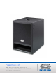
PowerSub 315 1000 WATTS POWERED SUBWOOFER 2x500 WATTS SATELLITE SPEAKER OUTPUTS Owner‘s Manual | Bedienungsanleitung
INHALTSVERZEICHNIS WICHTIGE SICHERHEITSHINWEISE WICHTIGE SERVICEHINWEISE BESCHREIBUNG AUSPACKEN & GARANTIE QUICK START BEDIENELEMENTE LEFT INPUT / RIGHT INPUT LEFT THRU, RIGHT THRU CLIP LED / SIGNAL LED X-OVER / SUB LEVEL LEFT / RIGHT SPEAKER OUTPUT EXTERNAL SUB OUTPUT POWER / MAINS IN SPECIFICATIONS / TECHNISCHE DATEN DIMENSIONS / ABMESSUNGEN BLOCK DIAGRAM SETUP EXAMPLE ....................... ....................... ....................... ....................... ....................... .................
WICHTIGE SICHERHEITSHINWEISE Das Blitzsymbol innerhalb eines gleichseitigen Dreiecks soll den Anwender auf nicht isolierte Leitungen und Kontakte im Geräteinneren hinweisen, an denen hohe Spannungen anliegen, die im Fall einer Berührung zu lebensgefährlichen Stromschlägen führen können. Das Ausrufezeichen innerhalb eines gleichseitigen Dreiecks soll den Anwender auf wichtige Bedienungs- sowie Servicehinweise in der zum Gerät gehörenden Literatur aufmerksam machen. 1. 2. 3. 4. 5. 6. 7. 8. 9. 10. 11. 12.
BESCHREIBUNG Herzlichen Glückwunsch! Sie haben sich mit dem PowerSub 315 von Dynacord für einen aktiven Subwoofer modernster Technologie entschieden. Der aktive 15“ Subwoofer PowerSub 315 mit vier integrierten Digitalendstufen mit einer Gesamtleistung von 2000W wurde speziell zum schnellen und einfachen Aufbau von Subwoofer-Satelliten-Systemen entwickelt. Bei Subwoofer-Satellitensystemen wird normalerweise ein Center Subwoofer und jeweils eine Satellitenbox links und rechts eingesetzt.
QUICKSTART QUICKSTART Achtung: Nach dem Aufbau der Anlage schalten Sie zuerst das Mischpult ein und schieben Sie die Masterfader am Mischpult auf den untereren Anschlag. Anschliessend können Sie den PowerSub 315 einschalten und mit den Ausgangsfadern die gewünschte Lautstärke einstellen. Ungewollt könnten Sie sonst bei eingeschalteter Signalquelle sehr hohen Schallpegeln ausgesetzt werden, die zu Gehörschädigungen führen könnten.
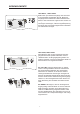
BEDIENELEMENTE LEFT INPUT , RIGHT INPUT Elektronisch symmetrische Eingänge zum Anschluss an hochpegelige Signalquellen wie z.B. Mischpultausgänge. Der Anschluß kann dabei wahlweise über Klinken- oder XLR-Stecker vorgenommen werden. Um etwaigen externen Brumm-, oder Hochfrequenzeinstreuungen vorzubeugen, sollte die Signaleinspeisung bevorzugt über hochwertige abgeschirmte Audiokabel mit XLR-Steckern erfolgen.
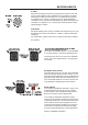
BEDIENELEMENTE X-OVER Mit diesem Schalter können Sie die Trennfrequenz zwischen dem Subwoofer und den Mittel-Hochton Satellitenboxen verändern. Die Werkseinstellung ist 100Hz und besonders für 12“ Satellitenboxen geeignet. Für Topteile mit 10“ oder 8“ Lautsprechern ist die 160Hz Einstellung vorteilhaft um eine mechanische Überlastung der kleinen Membranen zu vermeiden. Für Topteile mit 15“ Lautsprechern bietet die 80Hz Position häufig klangliche Vorteile.
BEDIENELEMENTE POWER Netzschalter zum Ein- und Ausschalten des Gerätes. Der Netzschalter ist beleuchtet, wenn der PowerSub 315 eingeschaltet ist. Sollte der Schalter nach dem Einschalten nicht leuchten, prüfen Sie zuerst ob das Netzkabel angesteckt und verriegelt ist. Ist dies der Fall und trotzdem keine Funktion vorhanden, kontaktieren Sie bitte ihren Fachhändler. MAINS IN Der netzseitige Anschluß ist mit einer PowerCon-Buchse ausgeführt.
Notes
CONTENTS IMPORTANT SAFETY INSTRUCTIONS IMPORTANT SERVICE INSTRUCTIONS DESCRIPTION UNPACKING & WARRANTY QUICK START CONTROLS LEFT INPUT / RIGHT INPUT LEFT THRU, RIGHT THRU CLIP LED / SIGNAL LED X-OVER / SUB LEVEL LEFT / RIGHT SPEAKER OUTPUT EXTERNAL SUB OUTPUT POWER / MAINS IN SPECIFICATIONS / TECHNISCHE DATEN DIMENSIONS / ABMESSUNGEN BLOCK DIAGRAM SETUP EXAMPLE 10 ....................... ....................... ....................... ....................... ....................... .......................
IMPORTANT SAFETY INSTRUCTIONS The lightning flash with arrowhead symbol, within an equilateral triangle is intended to alert the user to the presence of uninsulated ”dangerous voltage” within the product’s enclosure that may be of sufficent magnitude to constitute a risk of electric shock to persons. The exclamation point within an equilateral triangle is intended to alert the user to the presence of important operating and maintance (servicing) instructions in the literature accompanying the appliance.
DESCRIPTION Congratulations! With buying a Dynacord PowerSub 315 you have chosen a state-of-the-art active subwoofer that employs most advanced technology. The active 15” subwoofer PowerSub 315 with four integrated digital power amps provides total output power of 2000W and has been designed for the quick and easy set-up of subwoofer satellite systems. Subwoofer satellite systems normally employ a center woofer system and satellite cabinets on the left and right sides.
QUICKSTART QUICKSTART Caution: After system installation is complete, make sure to first power on the mixing console and to position the master faders at their lowest setting before switching the power of the PowerSub 315 to On. Use the output faders to establish the desired volume setting. Otherwise, switching and power-on noise or the high level audio signal of an inadvertently playing audio source could result in high acoustic outputs, that in some cases might even lead to hearing damage.
CONTROLS AND INDICATORS LEFT INPUT, RIGHT INPUT Electronically balanced inputs for the connection of high-level signal sources, like for example mixer outputs. Connecting signal sources via phone or XLR-type plug is equally possible.
CONTROLS AND INDICATORS X-OVER This switch lets you control the X-over frequency between subwoofer and Mid-High-range satellite cabinets. The factory setting (100Hz) is ideally suited for 12” satellite speaker systems. The 160Hz setting matches top cabinets and protects the 10” or 8” transducers’ diaphragms from mechanical overload. When employing top cabinets with 15” speakers, the 80Hz position mostly provides improved sound.
CONTROLS AND INDICATORS POWER Mains switch to power ON/OFF the unit. The mains switch lights when the PowerSub 315 is powered on and operational. If, after power on, the switch does not light, make sure the mains cord is correctly plugged in and locked in place. If the cord is correctly connected and operation is still not possible, contact your dealer. MAINS IN Mains connection is realized through a PowerCon-type socket. A 5m mains cord with PowerCon-type plug is supplied.
Specifications PowerSub 315 Amplifier PowerSub 1000 W / 8 Ohms (switchable to 2 x 500 W / 4 Ohms) 2 x 500 W / 4 Ohms 99 dB 129 dB LFS 1008 (364 853) 80 Hz, 100 Hz, 160 Hz 464 x 601 x 660 mm 45 kg 36 months Amplifier Power MID-HIGH SPL 1W/1m Max. SPL 1m (calculated) Sub Transducer Switchable X-Over Frequencies Dimensions W x H x D Weight Warranty Specifications Sub 115 Power Handling Impedance SPL 1W/1m Max.
BLOCK DIAGRAM 18
AUFBAUBEISPIELE / SETUP EXAMPLES D-LITE Musicians, Mobile DJ´s D 12 D 12 Configurations : ACTIVE 2-WAY Cabinet Types : 2x D 12, 1x PowerSub 315 Amplifiers : - Controllers : - Cables : 2x 4-pole long Accessories : 2x BS 50 2x 80° Horizontal Coverage : Total Amp Power : 2x 500 W + 1000 W = 2000 W 15 to 20 m Typical Distance : Options : - Comments : - PowerSub 315 D-LITE Musicians, Small Clubs D 12 D 12 Configurations : ACTIVE 2-WAY Cabinet Types : 2x D 12, 1x PowerSub 315, 1x Sub 1
AUFBAUBEISPIELE / SETUP EXAMPLES D-LITE Clubs, Bars, Bistros D 12 D 12 Configurations : ACTIVE 2-WAY Cabinet Types : 4x D 12, 1x PowerSub 315 Amplifiers : - Controllers : - Cables : 4x 4-pole long Accessories : 4x MB 212 (Wall-Mount) 4x 80° Horizontal Coverage : Total Amp Power : 2x 500W + 1000W = 2000W 15 to 20 m Typical Distance : Options : 2 additional Sub 115 can be driven Comments : D 12 in each corner, Center-Sub D 12 D 12 PowerSub 315 MP 7 or CMS D-LITE Musicians, Mobile DJ´
AUFBAUBEISPIELE / SETUP EXAMPLES D-LITE Musicians, Small Clubs D 12 D 12 Configurations : FULLRANGE Cabinet Types : 2x D 12, 2x Sub 115 Amplifiers : PowerMate 1000-2 Controllers : - Cables : 2x 4-pole long, 2x 4-pole short Accessories : 2x PCL 1500 2x 80° Horizontal Coverage : Total Amp Power : 2x 700W = 1400W 15 to 20 m Typical Distance : Options : Comments : one added Top or one added Sub can be driven on each side (3 x 8 ohms) PowerMate 1000-2 Sub 115 Sub 115 21
NOTES 22
Hinweise gemäß EN 61000-3-2:2000, EN 61000-3-11:2000, EN 55103-1:1997. Dies ist eine Einrichtung der Klasse A. Diese Einrichtung kann im Wohnbereich Funkstörungen verursachen; in diesem Fall kann vom Betreiber verlangt werden, angemessene Maßnahmen durchzuführen und dafür aufzukommen. Das Gerät unterliegt Sonderanschlussbedingungen. Das zuständige Elektrizitätsversorgungsunte rnehmen muß bestätigen, dass die Impedanz der Versorgung maximal 0,31 Ohm + j 0,19 Ohm ist.
DYNACORD 12000 Portland Avenue South, Burnsville, MN 55337, USA Phone: +1 952/844-4051, Fax: +1 952/884-0043 www.dynacord.com © Bosch Communications Systems Part Number F01U106899 Vs 02 Europe, Africa, and Middle East only. For customer orders, contact Customer Service at: +49 9421-706 0 Fax: +49 9421-706 265 Asia & Pacific only.