MIXER AMPLIFIER MV 503 MV 506 MV 512 Bedienungsanleitung Owner’s Manual Mode d’emploi Merkmale: • • 1 Eingang für 6,3mm Klinke, symmetrisch, umschaltbar Line/Mikro • 1 Eingang für 6,3mm Klinke, unsymmetrisch, umschaltbar Line/Mikro • 1 Cinch-Stereoeingang Line • 1 Ausgang “PRE OUT” • 1 Ausgang “TAPE OUT” • • 1 Eingang “MAIN IN” • • Vorrang der Eingänge 1, 2, 3 auf die anderen Eingänge, Kontaktaktivierung • Summensteller Höhen, Bässe und Lautstärke • Schutz gegen Kurzschluss am Ausgang •
Inhaltsverzeichnis Bedienungselemente und Funktionen . . . . . . . . . . . . . . . . . . . . . . . . . . . . . . . . . . . . . . Frontseite . . . . . . . . . . . . . . . . . . . . . . . . . . . . . . . . . . . . . . . . . . . . . . . . . . . . . . . . . . . . Rückseite . . . . . . . . . . . . . . . . . . . . . . . . . . . . . . . . . . . . . . . . . . . . . . . . . . . . . . . . . . . . Speisung mit Wechselstrom . . . . . . . . . . . . . . . . . . . . . . . . . . . . . . . . . . . . . . . . . . . . . .
FRONTSEITE BEDIENUNGSELEMENTE UND FUNKTIONEN 1. Lautstärkesteller für die Eingänge Diese Drehknöpfe erlauben die unabhängige Einstellung der Lautstärke der an die Eingänge “IN1", ”IN2", “IN3, IN4", “AUX IN” angeschlossenen Schallquellen. Durch die Rechtsdrehung jedes Knopfes wird die Lautstärke erhöht. Es wird empfohlen, den Knopf auf 0 zu stellen, wenn der betreffende Eingang nicht verwendet wird. 2.
RÜCKSEITE SICHERUNGSWERTE 8. Sicherung Bei Defekten oder bei Anschlußspannungswechsel darf das Ersetzen der Sicherung nur durch einen Fachmann erfolgen. Der neue Sicherungswert muß per Aufkleber auf der Rückwand angegeben werden. 9. Umschalter DC - AC 230V 115V MV 512 2,5A 5A MV 506 1,6A 3,15A MV 503 1A 2A Mit diesem Schalter kann die Batteriespannung Ein-und Ausgeschaltet werden. 10. Netzspannungs-Umschalter Das Gerät ist ab Werk auf 230V AC eingestellt.
ist, wenn Mikrofone verwendet werden, die keine externe Speisung erfordern: die auf den Anschlüssen 2 und 3 der XLR-Steckbuchse vorhandene Spannung könnte sonst schwere Schäden verursachen. 17. Empfindlichkeitsschalter für Eingang “IN1" Durch die Schaltung auf “MIC” kann an den Eingang “IN1" ein dynamisches Mikrofon angeschlosen werden; die Schaltung auf “LINE” erlaubt den Anschluß des Einganges “IN1" an eine Audioquelle mit hochpegeligern Signalausgang. 18.
23. Ausgangsklemme für zusätzlichen Lautsprecher An dieser Klemme kann ein kleiner zusätzlicher Lautsprecher angeschlossen werden; dieser wird mit dem gemischten Signal der Eingänge “IN4" und ”AUX-IN" angesteuert, über den geräteintern vorhandenen zusätzlichen Verstärker mit 1 W-Nominalleistung. Das Ausgangssignal unterliegt nur der Lautstärkeregulierung der Eingänge “IN4" und ”AUX-IN". 24.
ACHTUNG Es wird empfohlen, den Geräteanschluß ausschließlich von qualifizierten Fachkräften vornehmen zu lassen, die eine ausreichende technische Kenntnis, Erfahrung oder Fachausbildung besitzen um die Anschlüsse richtig auszuführen und so Stromgefahren vorzubeugen. Um die Gefahr von Stromschlägen zu vermeiden darf der Verstärker erst nach Beendigung aller Anschlüsse an das Stromnetz angeschlossen werden.
TECHNISCHE DATEN MV 503, MV 506, MV 512 Typ 30W - Mono - Tischgerät (MV 503) 60W - Mono - Tischgerät (MV 506) 120W - Mono - Tischgerät (MV 512) Ausgangsleistung nominal: 30 W - maximal: 45 W (MV 503) nominal: 60 W - maximal: 90 W (MV 506) nominal: 120 W - maximal: 180 W (MV 512) Nominalleistung bei 24Vdc-Speisung 25W (MV 503) 45W (MV 506) - 95W (MV 512) Übertragungsbereich 50 - 15.
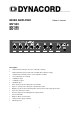
MIXER AMPLIFIER Owner’s manual MV 503 MV 506 MV 512 Description: • • 1 balanced 6.3mm input jack, line / micro switchable sensitivity • 1 unbalanced 6.
CONTENTS Controls and Functions . . . . . . . . . . . . . . . . . . . . . . . . . . . . . . . . . . . . . . . . . . . . . . . . . Front panel . . . . . . . . . . . . . . . . . . . . . . . . . . . . . . . . . . . . . . . . . . . . . . . . . . . . . . . . . . . Rear panel . . . . . . . . . . . . . . . . . . . . . . . . . . . . . . . . . . . . . . . . . . . . . . . . . . . . . . . . . . . AC Power supply . . . . . . . . . . . . . . . . . . . . . . . . . . . . . . . . . . . . . . . . . . . . . . . . . . . . . .
FRONT PANEL CONTROLS AND FUNCTIONS 1. input level controls These controls let you individually set the volume of the sound sources that are connected to the “IN 1", ”IN 2", “IN 3", ”IN 4", and “AUX IN”. Turning a control clockwise increases the volume of the corresponding source. We recommend to leave the controls of momentarily not used inputs at their minimal setting “0". 2.
REAR PANEL ADMISSIBLE VALUES (FUSE) 8. fuse In cases of defects or when the amplifier is going to be used on a different mains voltage, exchanging the fuse should be left to experienced service personnel. A label stating the value of the new fuse has to be attached to the appliance’s rear panel. 230V 115V MV 512 2,5A 5A MV 506 1,6A 3,15A MV 503 1A 2A 9. DC switch This switch lets you turn the battery supply on or off. 10. mains supply switch The amplifier is factory preset to 230 V AC.
mandatory to perform any plugging or unplugging of microphone cables with the phantom power turned off. Also make sure, that the phantom power is turned off when utilizing microphones that are not meant to be operated with phantom power. The voltage that is present on pin 2 and pin 3 of the XLR-connector could lead to severe damages on the microphones. When in doubt, please consult the owner’s manual of the questionable microphone or contact your dealer before you perform any connections. 17.
23. binding post for the connection of an additional loudspeaker This binding post is meant for the connection of a small external loudspeaker that gets driven by an internal auxiliary power amplifier, providing a nominal output of 1 watt. Only the mixed audio signal coming from the “IN 4" and the ”AUX IN" are included in the outputted signal. And hence to this fact, the volume is only controlled by the input controls of these two channels. 24.
CAUTION We strongly recommend that you leave the connection of the appliance to the qualified and experienced service technician who is specialized in connecting electrical and electronical equipment. Do not take the risk of electro-shock or shock hazard. To reduce the risk of electro-shock, all connections have to be accomplished before it is permissible to connect the amplifier to the mains supply.
SPECIFICATIONS MV 503, MV 506, MV 512 Typ 30W - Mono - Tabletop (MV 503) 60W - Mono - Tabletop (MV 506) 120W - Mono - Tabletop (MV 512) Output power nominal: 30 W - maximal: 45 W (MV 503) nominal: 60 W - maximal: 90 W (MV 506) nominal: 120 W - maximal: 180 W (MV 512) Nominal power with supply at 24VDc 25W (MV 503) 45W (MV 506) - 95W (MV 512) Frequency response 50 - 15.
MIXER AMPLIFIER Mode d’emploi MV 503 MV 506 MV 512 DESCRIPTON: • 1 entrée Jack 6,3 mm symétrique, sensibilité sélectionnable ligne / micro. • • 2 entrées microphoniques XLR symétriques, avec alimentation phantom 24 Vdc déconnectable. • 1 entrée RCA stéréo, sensibilité ligne. • 1 sortie “PRE OUT” • 1 sortie “TAPE OUT” • 1 entrée “MAIN IN” • • Priorité de l’entrée 1 sur les autres entrées à activation vocale.
Table des matières Potentiometres et Fonctions . . . . . . . . . . . . . . . . . . . . . . . . . . . . . . . . . . . . . . . . . . . . . Face Avant . . . . . . . . . . . . . . . . . . . . . . . . . . . . . . . . . . . . . . . . . . . . . . . . . . . . . . . . . . . Face Arriere . . . . . . . . . . . . . . . . . . . . . . . . . . . . . . . . . . . . . . . . . . . . . . . . . . . . . . . . . . Alimentation en courant Alternatif (SECTEUR) . . . . . . . . . . . . . . . . . . . . . . . . . . . . . . .
FACE AVANT POTENTIOMETRES ET FONCTIONS 1. Potentiomètres de réglage de niveau d’entrée Ces potentiomètres vous permettent de régler séparément le niveau des sources sonores reliées aux prises “IN 1", ”IN 2", “IN 3", ”IN 4" et “AUX IN”. Pour augmenter le niveau d’une source sonore, il suffit de faire tourner son potentiomètre dans le sens des aiguilles d’une montre. Nous vous recommandons de laisser sur ”0” les potentiomètres correspondant à des sources momentanément inutilisées. 2.
FACE ARRIERE 8. Fusible Le remplacement du fusible, que ce soit après une défaillance ou si vous désirez utiliser l’amplificateur sous une tension secteur différente, devrait être réalisé par un technicien expérimenté. Une fois ce remplacement effectué, il faut apposer sur la face arrière une étiquette indiquant la valeur du nouveau fusible. valeurs admissibles (fusible) 230V 115V MV 512 2,5A 5A MV 506 1,6A 3,15A MV 503 1A 2A 9.
REMARQUE Si vous branchez un micro câblé en asymétrique sur une entrée dont l’alimentation fantôme est activée, vous risquez d’endommager gravement le micro : prudence ! Il est impératif, dès que vous branchez ou débranchez un micro, de désactiver au préalable l’alimentation fantôme. De même, vérifiez toujours qu’elle est désactivée avant d’utiliser des micros qui n’en ont pas besoin. La tension présente entre les broches 2 et 3 du connecteur XLR peut endommager le micro.
. bornes “COM” Terminal commun des sorties (23) et (24). 23. borne pour la connexion d’un HP supplémentaire Cette borne sert à relier un petit haut-parleur externe, qui se trouve alors alimenté par un petit amplificateur de puissance auxiliaire interne, d’une puissance nominale de 1 Watt. Ce signal ne comporte que le mélange des prises “IN 4" et ”AUX IN". Par conséquent, le niveau d’écoute n’est déterminé que par les commandes d’entrée de ces deux voies. 24.
ATTENTION Nous vous recommandons expressément de laisser les branchements de l’appareil à un technicien de service qualifié et expérimenté, spécialisé dans la connexion d’appareils électriques et électroniques. Ne prenez pas le risque d’une électrocution ou d’un court-circuit. Afin de réduire les risques d’électrocution, toutes les connexions doivent être effectuées avant de relier l’amplificateur au secteur.
CARACTÉRISTIQUES MV 503, MV 506, MV 512 Type 30W - Mono - Tabletop (MV 503) 60W - Mono - Tabletop (MV 506) 120W - Mono - Tabletop (MV 512) Puissance de sortie nominale : 30 W - maximale : 45 W (MV 503) nominale : 60 W - maximale : 90 W (MV 506) nominale : 120 W - maximale : 180 W (MV 512) Puissance nominale sous 24 V 25W (MV 503) 45W (MV 506) - 95W (MV 512) Réponse en fréquence 50 - 15.
Notes 27
GARANTIE WARRANTY GARANTIE Das Werk leistet Garantie für alle nachweisbaren Material- und Fertigungsfehler für die Dauer von 12 Monaten ab Verkauf. Garantieleistungen werden nur dann anerkannt, wenn gültige, d.h. vollständig ausgefüllte Garantieunterlagen vorliegen. Von der Garantie ausgenommen sind alle Schäden, die durch falsche oder unsachgemäße Bedienung verursacht werden. Bei Fremdeingriffen oder eigenmächtigen Änderungen erlischt jeder Garantieanspruch.