OWNER‘S MANUAL BEDIENUNGSANLEITUNG MODE D‘EMPLOI
CONTENTS IMPORTANT SAFETY INSTRUCTIONS IMPORTANT SERVICE INSTRUCTIONS DESCRIPTION UNPACKING & WARRANTY INSTALLATION NOTES FRONT VIEW REAR PANEL INPUT POWER AMP OUTPUT GROUND-LIFT SWITCH MAINS INPUT ....................... ....................... ....................... ....................... ....................... ....................... ....................... ....................... ....................... ....................... .......................
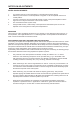
IMPORTANT SAFETY INSTRUCTIONS The lightning flash with arrowhead symbol, within an equilateral triangle is intended to alert the user to the presence of uninsulated „dangerous voltage“ within the product’s enclosure that may be of sufficient magnitude to constitute a risk of electric shock to persons. 1. 2. 3. 4. 5. 6. 7. 8. 9. 10. 11. 12. 13. 14. 15. 16.
DESCRIPTION Félicitations ! En achetant un amplificateur de puissance Dynacord Xa4000 vous avez choisi un appareil haut de gamme employant la technologie la plus avancée qui soit. L’amplificateur de puissance à deux voies Xa 4000 d’emploi universel combine la technologie Classe-H à une alimentation à commutation. Les amplificateurs de puissance Xa 4000 associent des performances audio inégalées, à un fonctionnement fiable et durable.
DESCRIPTION Sa construction mécanique et artisanale satisfait aux standards de fabrication de haute précision. Son châssis robuste est extrêmement rigide. Deux ventilateurs très performants à trois allures (off/slow/fast) garantissent une stabilité thermique totale avec un bruit très faible. La ventilation est dirigée de l’avant vers l’arrière ce qui permet un fonctionnement sans problème, même dans les armoires de racks les plus exiguës. L’entrée, symétrisée électroniquement s’effectue sur des embases XLR.
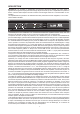
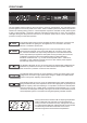
FRONT PANEL Use the POWER switch located on the front panel to power-on the appliance. The soft-start function protects against current inrush peaks on the mains, which in addition prevents the mains line protection switch from activating during power-on. The loudspeaker outputs are activated via relay switching with a delay of approximately 3 seconds to efficiently attenuate eventual power-on noise. The PROTECT LED lights during the delay time and the fans run at maximum speed.
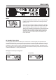
REAR PANEL INPUT The electronically balanced INPUT offers an input sensitivity of 0dBu (775mV) for direct connection of mixing consoles, equalizers, etc. The XLR-type connector OUTPUT is prepared for “throughconnecting” input signals to additional external power amps. The input signal is directly routed to the output connector. There are no repeaters or other electronic components within that signal path.
REAR PANEL POWER AMPLIFIER OUTPUT CONNECTORS Power amp output connection for SYSTEM, SUB and TOP channels is provided via professional SPEAKONtype output connectors. This mechanically and electrically safe connection method complies with any safety standard allowing the use of high-performance loudspeaker cables with diameters of up to 4 x 2.5mm2. The DYNACORD accessory program offers single connectors and couplings as well as high-performance loudspeaker cables.
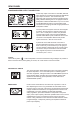
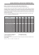
MAINS OPERATION & RESULTING TEMPERATURES MAINS OPERATION & RESULTING POWER AMP TEMPERATURES The following tables are useful in determining power supply and cabling requirements. The power drawn from the mains network is converted into acoustic output to feed the connected loudspeaker systems plus heat. The difference between drawn power and dispensed power is referred to as leakage power or dissipation (Pd).
NOTES ON ADJUSTMENTS NOTES ON ADJUSTMENTS 1. 2. 3. 4. 5. Turn the EQ controls on the mixing desk to a central position (linear setting). Switch any third-octave or octave equalisers to “Bypass” or set the equaliser controls to a central position. Connect a microphone and use the SUB and TOP control of the power amplifier to set the signal in such a way that the human voice sounds “natural”. This concludes the basic system setup.
GENERAL INSTALLATION NOTES GENERAL INSTALLATION NOTES • When installing a sound reinforcement system for halls or festival tents over their entire length, the loudspeaker systems have to be set up on the left and right sides of the stage, slightly pointing to the center, resulting in a beamshape coverage pattern over the length of the hall or festival tent. Placing Mid/Hi cabinets on both sides on top of each other (“STACKING”) provides improved long-throw coverage.
EXAMPLES FOR ACTIVE 2-WAY APPLICATIONS Fig. 1 Fig. 1 shows a standard setup consisting of 2x Xa 4000, 2x FX12 used as Mid/Hi cabinets and 4x FX 20 used as woofer cabinets. This all-purpose setup fulfills the requirements of most applications. The use of four FX 20 bass cabinets produces solid low-frequency sound reproduction, which is most favorable for revival and jazz-rock bands as well as for other bass drum-oriented musical styles when performed in medium size clubs or festival tents.
EXAMPLES FOR ACTIVE 2-WAY APPLICATIONS Fig. 3 Fig. 3 shows the possibility of how to achieve even higher SPL through employing an additional FX 20 woofer and Mid/Hi cabinets on each side of the stage. Additional cabinets are simply connected in parallel to the existing speaker systems. Of course, configuring woofers in a left-center-right setup – as outlines in Fig. 2 – is possible without problem.
BEDIENUNGSANLEITUNG
������ WICHTIGE SICHERHEITSHINWEISE WICHTIGE SERVICEHINWEISE BESCHREIBUNG AUSPACKEN & GARANTIE INSTALLATIONSHINWEISE FRONTSEITE RÜCKSEITE INPUT NF-VERBINDUNGSKABEL ENDSTUFENAUSGÄNGE GROUND-LIFT SCHALTER NETZEINGANG NETZBETRIEB & WÄRMEENTWICKLUNG EINSTELLHINWEISE AUFBAUHINWEISE BEISPIELE FÜR AKTIV 2-WEG ANLAGEN SPECIFICATIONS / TECHNISCHE DATEN BLOCK DIAGRAM DIMENSIONS / ABMESSUNGEN 16 ....................... ....................... ....................... ....................... ....................... ..
WICHTIGE SICHERHEITSHINWEISE Das Blitzsymbol innerhalb eines gleichseitigen Dreiecks soll den Anwender auf nicht isolierte Leitungen und Kontakte im Geräteinneren hinweisen, an denen hohe Spannungen anliegen, die im Fall einer Berührung zu lebensgefährlichen Stromschlägen führen können. 1. 2. 3. 4. 5. 6. 7. 8. 9. 10. 11. 12. 13. 14. 15. 16.
BESCHREIBUNG Herzlichen Glückwunsch! Sie haben sich mit der Endstufe Xa 4000 von DYNACORD für ein Gerät modernster Technologie entschieden. Die Xa 4000 ist eine universell einsetzbare Aktiv 2-Weg Endstufe in Class H Technologie mit Schaltnetzteil. Die Endstufen XA 4000 vereinen überragende Audio-Performance mit höchster Zuverlässigkeit und Betriebssicherheit.
BESCHREIBUNG Höchste Präzision ist auch in der mechanischen Konstruktion und Verarbeitung gewährleistet. Das robuste Chassis ist besonders verwindungssteif. Die thermische Stabilität wird durch zwei 3-Stufen Lüfter (off/slow/fast) mit sehr niedrigem Geräuschpegel gewährleistet. Die Front-to-Rear Luftführung, erlaubt den Betrieb auch in großen und schmalen Endstufen-Racks. Der Eingang ist elektronisch symmetrisch auf eine XLR-Buchse geführt.
FRONTSEITE Mit dem POWER Schalter auf der Frontblende wird das Gerät eingeschaltet. Eine Softstart- Schaltung vermeidet dabei Einschaltstromspitzen auf der Netzleitung. Dadurch wird verhindert, dass der Leitungsschutzschalter des Stromnetzes beim Einschalten der Endstufe anspricht. Die Lautsprecher werden über die Ausgangsrelais um ca. 3 Sekunden verzögert zugeschaltet, wodurch etwaige Einschaltgeräusche effektiv unterdrückt werden, die ansonsten in den Lautsprechern hörbar wären.
RÜCKSEITE INPUT Der Eingang INPUT ist elektronisch symmetrisch mit einer Eingangsempfindlichkeit von 0dBu (775mV) für den direkten Betrieb mit Mischpulten, Equalisern usw. ausgelegt. Die XLR-Ausgangsbuchse OUTPUT ist zum „Durchschleifen“ des Eingangssignals zu weiteren Endstufen vorgesehen. Das Eingangssignal wird dabei direkt auf die Ausgangsbuchse gelegt, es befinden sich keine Zwischenverstärker oder andere elektronischen Bauteile in diesem Pfad.
RÜCKSEITE ENDSTUFENAUSGANGSBUCHSEN Die Endstufenausgangsbuchsen SYSTEM, SUB und TOP sind professionelle SPEAKON Ausgangsbuchsen. Diese mechanisch und elektrisch sichere Verbindung wird allen Sicherheitsanforderungen gerecht und erlaubt die Verwendung von Hochleistungslautsprecherkabeln von bis zu 4 x 2,5mm2 Querschnitt. Im DYNACORD Zubehörprogramm finden Sie Einzelstecker und Kupplungen sowie Hochleistungslautsprecherkabel. Die Systembuchse ist vierpolig belegt.
NETZBETRIEB & WÄRMEENTWICKLUNG IN DER ENDSTUFE NETZBETRIEB & WÄRMEENTWICKLUNG IN DER ENDSTUFE Mit Hilfe der folgenden Tabellen können die Anforderungen für Stromversorgung und Zuleitungen bestimmt werden. Die vom Stromnetz aufgenommene Leistung wird in Ausgangsleistung für die Lautsprecher und in Wärme umgewandelt. Die Differenz aus aufgenommener Leistung und abgegebener Leistung nennt man Verlustleistung (Pd). Die durch Verluste entstehende Wärme verbleibt u.U.
EINSTELLHINWEISE EINSTELLHINWEISE 1. Klangregler am Mischpult auf Mittelstellung (lineare Einstellung) drehen. 2. Vorhandene Terz- oder Oktavequaliser auf “Bypass” schalten oder Equaliserregler auf Mittelstellung schieben. 3. Mikrofon anschließen und mit dem SUB- und TOP-Regler an der Endstufe das Signal so einstellen daß die menschliche Stimme “natürlich” klingt. 4. Die Grundeinstellung der Anlage ist hiermit abgeschlossen. 5.
AUFBAUHINWEISE AUFBAUHINWEISE FÜR AKTIV 2-WEG ANLAGEN • Zur Beschallung von Hallen oder Zelten von der Schmalseite her werden die Boxen links und rechts, leicht nach innen gedreht, auf die Bühne gestellt. Durch diese Anordnung ergibt sich eine scheinwerferartige Abstrahlcharakteristik in Längsrichtung der Halle oder des Zeltes. Müssen größere Reichweiten erzielt werden, so sollten die Mittel-Hochtonboxen auf jeder Seite übereinander gestellt werden („STACKING“).
BEISPIELE FÜR AKTIV 2-WEG ANLAGEN Abb. 1 Abbildung 1 zeigt eine Standardanlage bestehend aus 2x Xa 4000, 2x FX12 als Mittel-Hochtonboxen und 4x FX 20 als Bassboxen, die für die verschiedensten Anwendungen universell einsetzbar ist. Durch die Verwendung von 4 FX 20 Basskabinetten ergibt sich ein solides Bassfundament das für Coverbands, Jazzrock und Bassdrum-orientierte Stilrichtungen in mittelgroßen Clubs und Zelten Verwendung findet.
BEISPIELE FÜR AKTIV 2-WEG ANLAGEN Abb. 3 Abbildung 3 zeigt eine Möglichkeit durch die Verwendung von je einer weiteren Bassbox FX 20 und MittelHochtonbox links und rechts noch mehr Schalldruck zu erzielen. Die weiteren Kabinette werden einfach parallel an die anderen Boxen angeschlossen. Natürlich kann mit den Bassboxen wie in Abbildung 2 auch problemlos ein Left-Center-Right Aufbau realisiert werden. Die Mittel-Hochtonboxen können wie abgebildet „gestackt“, also übereinander aufgestellt werden.
MODE D‘EMPLOI
TABLE DES MATIÈRES INSTRUCTIONS DE SÉCURITÉ IMPORTANTES INSTRUCTIONS DE RÉPARATION IMPORTANTES DESCRIPTION DÉBALLAGE ET GARANTIE REMARQUES CONCERNANT L‘INSTALLATION FACE AVANT ARRIÈRE INPUT CORDONS DE CONNEXION AUDIO NECTEURS DE SORTIE DE L’AMPLIFICATEUR DE PUISSANCE COMMUTATEUR GROUND-LIFT ENTRÉE SECTEUR FONCTIONNEMENT SUR LE SECTEUR ET TEMPÉRATURES RÉSULTANTES REMARQUES SUR LES RÉGLAGES REMARQUES SUR L‘INSTALLATION EXEMPLES D‘APPLICATIONS ACTIVES À 2 VOIES CARACTÉRISTIQUES ET DONNÉES TECHNIQUES SCHÉMA DE
INSTRUCTIONS DE SÉCURITÉ IMPORTANTES Le symbole représentant un éclair fléché dans un triangle équilatéral a pour but d’alerter l’utilisateur de la présence d’une „tension dangereuse“ non isolée à l’intérieur du boîtier, pouvant être d’une force suffisante pour constituer un risque d’électrocution. 1. 2. 3. 4. 5. 6. 7. 8. 9. 10. 11. 12. 13. 14. 15. 16.
DESCRIPTION Félicitations ! En achetant un amplificateur de puissance Dynacord Xa4000 vous avez choisi un appareil haut de gamme employant la technologie la plus avancée qui soit. L’amplificateur de puissance à deux voies Xa 4000 d’emploi universel combine la technologie Classe-H à une alimentation à commutation. Les amplificateurs de puissance Xa 4000 associent des performances audio inégalées, à un fonctionnement fiable et durable.
DESCRIPTION Sa construction mécanique et artisanale satisfait aux standards de fabrication de haute précision. Son châssis robuste est extrêmement rigide. Deux ventilateurs très performants à trois allures (off/slow/fast) garantissent une stabilité thermique totale avec un bruit très faible. La ventilation est dirigée de l’avant vers l’arrière ce qui permet un fonctionnement sans problème, même dans les armoires de racks les plus exiguës. L’entrée, symétrisée électroniquement s’effectue sur des embases XLR.
FACE AVANT Utilisez l‘interrupteur POWER situé sur la face avant pour mettre l’appareil sous tension. La fonction de temporisation Soft-Start le protège des sautes de courant, ce qui de plus évite l’activation du circuit de protection interne lors de la mise sous tension. Les sorties haut-parleur sont activées via une commutation par relais avec un délai d’approximativement 3 secondes de manière à atténuer efficacement d’éventuels bruits de commutation.
ARRIÈRE INPUT L‘entrée (INPUT), symétrisée électroniquement, offre une sensibilité d‘entrée de 0 dBu (775 mV) pour le branchement direct de consoles de mixage, égaliseurs, etc. La prise de sortie (OUTPUT) de type XLR est préparée au branchement “en transit” (thru connection) des signaux d’entrée vers d’autres amplis de puissance. Le signal d’entrée est envoyé directement au connecteur de sortie. Il n’y a aucun répétiteur ou autre composant électronique dans le parcours de ce signal.
ARRIÈRE CONNECTEURS DE SORTIE DE L‘AMPLIFICATEUR DE PUISSANCE Les canaux de sortie SYSTEM, SUB et TOP de l‘amplificateur de puissance sont équipés de connecteurs de type SPEAKON. Cette méthode de branchement, mécaniquement et électriquement sûre satisfait à tous les standards de sécurité et permet l‘usage de câbles de haut-parleur très performants ayant des diamètres pouvant aller jusqu‘à 4x2,5mm2.
FONCTIONNEMENT SUR LE SECTEUR ET TEMPÉRATURES FONCTIONNEMENT SUR LE SECTEUR ET TEMPÉRATURES RÉSULTANTES Les tableaux suivants vous apporteront une aide précieuse dans la détermination du choix de l’alimentation et des câbles Le courant secteur est converti en signal de sortie afin d’alimenter les haut-parleurs connectés mais aussi en chaleur. La différence entre le courant utilisé et la puissance restituée est appelée perte de puissance ou dissipation (Pd).
REMARQUES SUR LES RÉGLAGES REMARQUES SUR LES RÉGLAGES 1. 2. 3. 4. 5. Régler en position centrale les contrôles d’égalisation de la console de mixage (réglage linéaire) Régler en position “bypass” tout égaliseur, qu’il soit de type tiers d’octave ou octave, ou régler les contrôles d’égalisation en position centrale. Brancher un microphone et utiliser les contrôles SUB et TOP de l’amplificateur de puissance pour régler le signal de manière à obtenir une voix humaine “naturelle”.
REMARQUES GÉNÉRALES SUR L‘INSTALLATION REMARQUES GÉNÉRALES SUR L‘INSTALLATION • Lors de l’installation d’un système de sonorisation dans des salles ou des chapiteaux de festival sur toute leur longueur, les haut-parleurs doivent être placés, de chaque côté de la scène, et dirigés légèrement vers le centre, afin de couvrir toute la longueur de la salle ou du chapiteau d‘un faisceau sonore.
EXEMPLES D‘APPLICATIONS ACTIVES À 2 VOIES Fig. 1 La Fig. 1 montre une configuration composée de 2 XA 4000, de 2 FX12 utilisées comme enceintes Mid/Hi et de 4 FX 20 employées comme woofer. Cette configuration polyvalente satisfait aux exigences de la plupart des applications.
EXEMPLES D‘APPLICATIONS ACTIVES À 2 VOIES Fig. 3 La Fig. 3 montre comment obtenir un niveau sonore encore plus élevé en employant d‘autres woofers FX 20 et enceintes Mid/HI de chaque côté de la scène. Les enceintes supplémentaires sont simplement reliées en parallèle au système de haut-parleurs existant. Bien entendu, disposer les woofers dans une configuration gauche-centre-droite, comme décrit à la Fig. 2, est possible sans aucun problème.
SPECIFICATIONS Amplifier at rated conditions, both channels driven, 8Ω loads, unless otherwise specified. Xa 4000 Load Impedance Maximum Midband Output Power THD = 1%, 80Hz SUB, 1kHz TOP, Single Channel Rated Output Power THD < 0.1%, 20Hz-140Hz SUB, 140Hz-20kHz TOP Single Channel SUB TOP 2Ω 4Ω 8Ω 2Ω 4Ω 8Ω 1800W 1100W 600W 1600W 900W 500W ---- 1000W 500W --- 800W 400W Maximum RMS Voltage Swing THD = 1%, 80Hz SUB, 1kHz TOP 78V Power Bandwith THD = 1%, ref.
BLOCK DIAGRAM 43
DIMENSIONS 44
NOTES 45
NOTES 46
NOTES 47
BOSCH Communications Systems USA Telex Communications Inc., 12000 Portland Ave. South, Burnsville, MN 55337, Phone: +1 952-884-4051, FAX: +1 952-884-0043 Germany EVI AUDIO GmbH, Hirschberger Ring 45, D 94315, Straubing, Germany Phone: +49 9421-706 0, FAX: +49 9421-706 265 France: EVI AUDIO France, Parc de Courcerin, Allée Lech Walesa, 77185 Lognes, France, Tél: +33 1 64800090, FAX: +33 1 6006 5103 Subject to change without prior notice. www.eviaudio.