
User manual
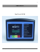

Operating & Installation Manual for the GSC300 Engine Controller
14
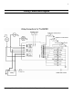
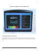
3: NOT IN AUTO: When the controller is in the OFF Mode, the NOT IN AUTO LED will illuminate and
the NOT IN AUTO Output will close to +Vbatt, indicating the controller is not in the AUTO Mode. The LCD
display will read “OFF”, however the backlight on the LCD display will not be ON.
NOTE:
+ Battery must be permanently connected to the AUTO terminal for the NOT IN AUTO condition
and LED indications to function properly.
4: LOW BATTERY VOLTAGE ALARM: In the event the battery voltage drops below the user
defined set point which can be between 7 and 35VDC, the engine controller displays a Low Battery Condition.
The Low Battery Voltage condition can occur when the controller is in the AUTO or MANUAL/TEST Mode,
but will only occur in the running state or while in standby in AUTO. The LCD display will show the message:
“LOW_BATT”
5: LOW OIL INPUT: The Low Oil Input can accept data from a sender or signal from a N.O. or N.C. type
switch. N.O. means that ground would be a failure, +5V would be “Engine OK”. N.C. means that ground
would be “Engine OK”, and +5V would be a failure. The operation of the oil input is set in PSI by the PC
Interface and is the only input which has selectable operation in this manner.
Note:
The oil input failure is disabled during the Oil Bypass time.
6: HIGH TEMPERATURE INPUT: For proper operation this must be of the standard N.O. type where
with a switch or sender, a ground would be seen as a failure, and a +5V would be seen as “Engine OK”. This
can be used with a sender or switch and when using a sender the failure point in degree Fahrenheit can be
adjusted using the PC Interface.
7: FUEL LEVEL/AUXILIARY INPUT: For proper operation while using a switch, the switch must
be the N.O. type which closes to ground upon failure. If this input is used as a sender, no failure will be
indicated. The sender option is solely for Fuel Level/Auxiliary Level Display on the LCD.
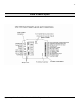
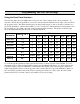
8: SPEED SIGNAL SENSITIVITY: The controller will accept to a maximum of 300 VAC, 60 Hz from
direct generator output for speed sensing. The following values are minimal recommended voltages for speed
signal sensing:
20 HZ - .075 V (75mV)
60 HZ - .6V (600mV)
9: HOUR METER: The controller can display a log of generator run times. Run times will be displayed on
the controllers display screen. The display represents both hours and minutes in the form 123456:7. The last
digit on the hour meter will represent the time in 1/10 of an hour. Each increment would represent 6 minutes.
For example if the hour meter displays 000010:5 than the generator had ran for 10 hours and 30 minutes.
Please note that although the hour meter displays time in hours and minutes, it will record up to the nearest
second. If the generator was operated for only 3 minutes, the display may not increment but this time would be
stored and added to the next generator run time.
10: MAGNETIC PICK-UP CAPABILITY OPTION: The Magnetic Pick-Up Capability Option can
be provided on the GSC300 upon request. Frequency will not be displayed on the LCD if this option is chosen.