
User manual


11 of 28
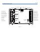
14
Low Oil Output closes to +12/24VDC upon Low Oil Failure.
15
Low Battery Output closes to +12/24VDC on Low Battery Condition. When a low
battery condition is detected this output turns on immediately. When the low battery
condition is removed this output remains on for 5s before turning off.
16
Engine Run Output closes to +12/24VDC on Engine Run Condition.
17
Not In Auto Output closes to +12/24VDC when unit is not in auto.
18
General Failure Output closes to +12/24VDC on a General Failure.
19
Start Stop Input (i.e. Remote Start Contacts). Apply +12/24VDC to this terminal while
unit is in Auto Mode to start engine. Remove +12/24VDC to stop engine or enter Cool-
Down mode.
Maximum distance for the remote start contacts
There is no absolute maximum since this depends on the size and type of the wire
used. There needs to be a minimum voltage of 8VDC at the Start/Stop input for a
start to be detected. The wiring should be rated assuming a maximum 0.1A current
draw.
There could be large voltage drops over long distances. Mounting an external relay
close to the controller and controlling it with the remote switch is a good solution.
20 - 22
Sensor Inputs
Engine Sensor type MUST be selected and programmed properly to GSC300 (switch
or sender type). Failure to do so may result in the controller not shutting down on true
engine failure (Low oil pressure or high engine temperature).
When installing engine sensors (oil pressure, engine temperature, fuel level) ensure
the switches are connected to ground circuit through the engine sensor. Damage
will occur to controller unit if the sensor input terminals (Terminal #’s 20, 21 and 22) are
connected to +Battery.
When using engine sensors that are the resistive type the proper manufacturer of
the sender MUST be selected during programming. Failure to select the correct
manufacturer type will cause inaccurate readings as well as failure to protect the
engine during a fault condition.
20
Low Oil Pressure sensor input. This sensor can be the resistive type (Sender) or can
be the switch type. The proper type of sensor must be selected during GSC300
controller programming. The sender or switch must be connected to ground for proper
operation. If +Battery is connected to input terminal this can result in damaged to
GSC300 controller. When using a sender, the proper sender manufacturer must be
selected as each sender manufacturer’s characteristics are different; the sender failure
set-point must also be selected. When using a switch NO or NC much be selected from
the programming menu. NO refers to the state of the contacts during normal engine
operation, therefore NO refers to normally open at normal engine run and close to
ground on low oil pressure failure.