
User manual


22 of 28
6. Technical Notes and FAQ
6.1 Controller Memory Clear Time
The GSC300 needs 10 seconds for its memory to clear. When the power to the controller is turned off and
then back on again without waiting 10 seconds to clear the memory, a loss of speed will may be indicated by
the GSC300 (if controller is in AUTO mode and start signal is activated) because the controller remains in run
mode and senses that the generator has stopped. This would be indicated by a Flashing Overspeed LED. By
leaving the GSC300 main power OFF for 10 seconds before main power is re-applied this allows the clearing
the memory and it will function as intended.
6.2 Step Down Transformer Use On Speed Sensing Cable With Inverter Systems
In some applications engine controllers are used on generators where there is no utility connection and
inverters are used to provide AC power instead of a utility. Inverters can produce harmonics that can cause
small AC signals to appear on wires that are near any power lines being fed by the inverter. If the generator
output wires are located close to a line being powered by an inverter, a small AC signal can appear on the
generator output lines when the inverter is on. This signal can cause the engine controller to react as if the
generator is running if the speed sensing wires are connected to the generator output lines. This small AC
signal can cause the controller to appear to have a Low Oil Failure when the remote start contacts are closed
or the controller is put in the manual/test mode. The controller may think the generator is already running and
immediately check to make sure there is oil pressure. Since the engine really hasn’t started yet, there is no oil
pressure and the controller sees a low oil fault. This is seen as the Oil LED turning on steady even before the
engine starts to engage the starter.
Without this false speed signal the controller will not look for oil pressure until the engine has started to run
and the crank disengages if oil verification is disabled. Simply installing a small transformer between the
generator output and the speed sensing terminals on the controller can eliminate this false speed signal. This
transformer should be rated for 120 or 240 volts on the input or primary coil (depending on the generator
output voltage you are using for speed sensing), and have an output voltage of around 12VAC on the
secondary of the transformer. The two wires from the secondary of the transformer are connected to the two
wires of the speed sensing terminals on the GSC300 controller. The step-down transformer acts to reduce the
false speed signal on the line to a level that the engine controller will not recognize as the engine running. A
common size transformer that would serve this purpose would be 24VA.
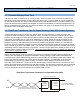
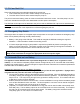
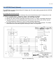
Step Down Transformer Connections on Speed Sensing Cable
#9
#10
12VAC
Secondary
Winding
Step Down Transformer
120VAC
Primary
Winding
To Generator Output
Line to Neutral 120VAC
Twisted pair of wires connected to
speed sensing terminals on GSC300