
User manual


7 of 28
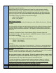
2. Wiring Installation Guidelines
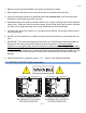
Danger: Never work on the engine while its power is on. This controller
does not generate a warning signal prior to automatic engine start. Warning
signs should be placed on engine equipment indicating this important safety
measure.
2.1 Mounting
See section 6.7 on page 26 for the GSC300 mounting dimensions. The maximum torque is 7in-lbs
for the three GSC300 mounting screws.
2.2 General
Following these instructions will help avoid common installation problems during wiring and setup.
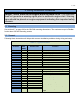
Table 2 – Types and Sizes
Terminal
Wire
Size
(AWG)
Current max.
Function
1
12
12V/40A, 24V/20A
Fuel Output Terminal
2
12
12V/40A, 24V/20A
Auto(Battery +) Terminal Connection
3
12
12V/40A, 24V/20A
Auto(Battery +) Terminal Connection
4
12
12V/40A, 24V/20A
Crank Output Terminal
5
12
12V/40A, 24V/20A
Ground Terminal Connection
6
12
12V/40A, 24V/20A
Ground Terminal Connection
7
12
12V/40A, 24V/20A
Preheat/ETS Terminal
8
12
12V/40A, 24V/20A
Preheat/ETS Terminal
9
18
100mA
Speed Signal Connection
10
18
100mA
Speed Signal Connection
11 - 18
18
Sum of current for outputs 11 to 18 cannot exceed 350mA.
11
18
300mA
Overcrank (failure to start) Output
12
18
300mA
Overspeed Output
13
18
300mA
High Temp Output
14
18
300mA
Low Oil Output
15
18
300mA
Low Battery Output
16
18
300mA
Engine Run Output
17
18
300mA
Not in Auto Output
18
18
300mA
General Failure Output
19
18
7mA
Start/Stop Input
20
18
7mA
Oil Pressure Sender/Switch Input
21
18
7mA
Temperature Sender/Switch Input
22
18
7mA
Fuel Level/Auxiliary Sender/Switch
Input