
User manual


8 of 28
1. Battery must be disconnected before any wiring connections are made.
2. Wire length from the engine to the controller should not exceed 6 meters (20 feet).
3. Wiring size and type should be as specified below. Use stranded wire, since solid wire has a
tendency to crack, break and loosen over time.
4. WARNING: Relays are rated for maximum 40A at 12V. If relays are being used at 24V maximum
rating is 20A. Relays are rated for resistive ratings. When driving such loads as starter solenoids
you must ensure proper de-rating of the relays. Consult factory for further details.
5. The sum of the current for outputs 11 to 18 cannot exceed 350mA. Each output cannot exceed
300mA individually.
6. DO NOT use wire smaller than 18 AWG as smaller wire has a tendency to crack and break over
time.
7. IMPORTANT: The connections supplying DC power to the GSC300 panel should preferably run
directly from the battery posts with no splices or other connections. Avoid using chassis
(aluminum or iron engine parts), as return conductor for battery negative voltage. Copper wiring
is recommended. Failure to follow the above may result in erratic operation due to large voltage
drops across wiring connections. A small fuse should be placed at the battery terminal to provide
12 volts to the Remote Start Contacts to ensure that a short along this line will not cause any
damage.
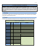
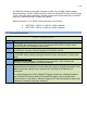
8. Follow all instructions / guidelines given in Table 3 below for the individual terminals.
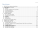
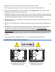
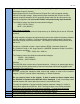
2.3 GSC300 12/24VDC System Operation
4
3
5
2
6
1
7
8
40 A40 A40 A
PRE-HEAT
12VDC
RELAYS
RELAY
FUEL
RELAY
CRANK
RELAY
9 10
22
21
20
19
18
17
16
15
14
13
12
11
4
3
5
2
6
1
7
8
40 A40 A40 A
PRE-HEAT
24VDC
RELAYS
RELAY
FUEL
RELAY
CRANK
RELAY
9 10
22
21
20
19
18
17
16
15
14
13
12
11
! !
12VDC RELAYS MUST
BE INSTALLED FOR 12VDC
SYSTEM OPERATION
24VDC RELAYS MUST
BE INSTALLED FOR 24VDC
SYSTEM OPERATION
Figure 1