
User manual


9 of 28
The GSC300 controller is designed to operate in either 12 or 24VDC system voltages.
When operating in 12VDC systems the Fuel, Crank and Preheat/ETS relays need to be the
12VDC relay type. When operating in 24VDC systems these relays need to be the 24VDC
relay type. Contact the factory if relays are required.
Approved relays for 12 or 24VDC system operation are as follows:
AZETTLER – AZ973-1C-12DC for 12VDC operation
AZETTLER – AZ973-1C-24DC for 24VDC operation
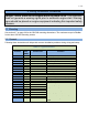
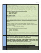
2.4 Terminal Description
Table 3 – GSC300 Terminals
Term #
Description
1
Fuel Output provides 12V/40A or 24V/20A maximum. Fuel Output closes to
+12/24VDC when start signal is received, and opens when either an engine failure
occurs or when Cool Down period has ended.
2 , 3
Battery Positive Terminals. Main +Battery power connection to controller. These
terminals are internally connected together on GSC300 controller.
4
Crank Output provides 12V/40A or 24V/20A maximum. Crank Output closes to
+12/24VDC during cranking, and opens when the engine has started, or during Crank
Rest.
5 , 6
Main Battery Ground connection for the controller module. A good ground connection,
directly from the battery, is required for proper operation. These terminals are
internally connected together on GSC300 controller.
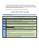
7 , 8
Preheat/ETS Output provides 12V/40A or 24V/20A maximum. It provides a set of dry
contacts between terminals #7 and #8. When this output is energized terminals #7 and
#8 are connected together. When output is OFF terminals #7 and #8 have no
connection.
To verify the operation of the Preheat/ETS Output, measure the resistance between
the Preheat/ETS terminals when the Preheat/ETS Output is ON, it should read a
closed circuit (i.e. zero ohms). When the output is OFF there should be an open circuit
between the terminals (very high resistance).