GSC400 PC INTERFACE SOFTWARE MANUAL Installation and User Manual for the GSC400 PC Software Interface File: GSC400ConfigRev1.0.doc Feb.
Thank You for purchasing this DynaGen product Please read manual before programming Unit End-user Agreement for GSC400 PC Interface software. GRANT OF RIGHTS DynaGen Technologies grants you the following non-exclusive rights: You may install and use the enclosed software product on your computer for reading and configuration of the GSC400 engine controller.
Table of Contents 1.0 Welcome 4 2.0 Installing the GSC400 software 2.1 Before you begin 2.2 Minimum hardware requirements 2.3 Installing on Windows 4 3.0 Connecting the GSC400 to your PC 7 4.0 Using the GSC400 PC interface software 4.01 Starting the PC interface software 4.02 GSC400 monitor interface screen 4.03 GSC400 update interface screen 4.3.1 Engine logic 4.3.2 Analog inputs 4.3.3 Digital I/O 4.3.4 Batttery 4.3.5 Speed 4.3.6 Generator 4.3.7 J1939 4.3.8 Misc 4.04 GSC400 failure log screen 4.
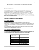
PC INTERFACE SOFTWARE INSTRUCTIONS Section 1 – Welcome The GSC400 PC software interface is a program which allows programming and customization to DynaGen’s GSC400 Engine Controllers. The GSC400 can be programmed manually via front panel buttons OR with the easy-to-use PC software interface which allows customization of inputs, outputs; AC sensing, engine logic settings, and much more.
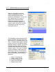
2.3 – Installing on Windows 98SE, 2000, ME, XP. 1. Exit all open applications, close any open windows, and disable any virus protection software before installing the GSC400 software. (Consult the instructions that came with your virus protection software.) If you have a previous version of the GSC400 PC Interface installed on your PC then you should uninstall the current version before installing the newer one. 2. Insert the GSC400 PC Interface CD into your CD-ROM drive.
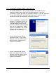
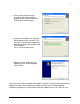
5. Click Install to continue setup installation which will install the program to the confirmed locations. Click Back to make changes. 6. A process bar displays the software being copied to your hard drive. This may take several minutes depending upon the speed of your computer and CD-ROM drive. Press Cancel to abort setup. 7. Upon successful installation, the following screen will be displayed. Click finished You have successfully installed the GSC400 PC interface.
Section 3 – Connecting the GSC400 to your PC. WARNING: NEVER CONNECT THE GSC400 PROGRAMMING CABLE INTO THE UNIT IF THE GSC400 IS POWERED ON. The GSC400 is easily connected to your PC for Reading, Configuration and programming. The GSC400 has a serial programming connector, which is identified on the labeling. A GSC400 programming cable must be used between the GSC400 controller and the PC for monitoring and programming capabilities.
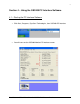
Section 4 – Using the GSC400 PC Interface Software. 4.1 – Starting the PC Interface Software 1. Click Start, Programs, DynaGen Technologies, then GSC400 PC Interface. 2. You will now see the GSC400 Monitor PC Interface screen.
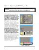
4.2 – GSC400 Monitor Interface Screen When the GSC400 PC Interface software is opened on the PC, the default GSC400 Monitor screen window will be displayed. The user has many options from this screen to choose from including GSC400 monitoring, updating, failure logs, security and firmware upgrades. To monitor, read or write to the GSC400 the controller must be successfully connected to the PC. The GSC400 must be configured to the correct COM port setting for successful data transfer.
When the GSC400 is successfully connected to the PC for data transfer, the engine and generator status may be displayed within the interface screen. The monitoring status can be displayed by clicking the “Start Monitor” button located at the bottom of the GSC400 interface screen. When monitoring engine and generator status digital inputs and outputs are also monitored. Inputs and outputs 1 thru 8 will depend upon the configuration of the GSC400 settings.
4.3 – GSC400 Update Interface Screen Data transfer between the GSC400 and the PC software interface may be achieved by clicking the proper buttons on the bottom of the interface screen. Data may be read from the GSC400 and displayed within the PC interface screen or data displayed in the PC interface screen may be programmed to the GSC400. Storing or reading specific data such as engine logic, inputs, outputs, battery, speed, generator, J1939 or misc can be obtained by using the appropriate buttons.
The GSC400 Update screen allows configuration to the following parameters: 1. 2. 3. 4. 5. 6. 7. 8. Engine Logic Analog Inputs Digital I/O Battery Speed Generator J1939 Misc 4.3.
Function Description Delay to Start The time in seconds that the GSC400 will wait before starting the generator. Time in seconds that the GSC400 will preheat the engine. Preheat occurs before the engine cranking cycle. Time in seconds the GSC400 will continue to crank the generator. The controller will engage the flywheel until engine start or the crank time expires. Time in seconds that the GSC400 will preheat the engine.
4.3.2 – Analog Inputs The GSC400 Analog Input screen allows configuration to the following inputs: 1. 2. 3. 4. 5. 6.
Function Input Pin Signal Source Bypass Delay Switch Setting Shorted Sender Open Sender Units Warning Level Failure Level Description Input 2-7 may be configured to a specific input. A specific function can be assigned to more then one input pin to allow a greater current output. If using a sender be careful to select a Low or High input impedance location to correspond to the sender specifications. Reserve may be selected to configure proper setting without assigning an active input.
4.3.3 – Digital I/O The GSC400 Digital I/O screen allows configuration to the following: Digital Input: 1. Input A 2. Input B 3. Input C 4. Input D 5. Input E 6. Input F 7. Input G 8. Input H Digital Output: 1. Output A 2. Output B 3. Output C 4. Output D 5. Output E 6. Output F 7. Output G 8.
4.3.4 – Battery The GSC400 Battery screen allows configuration to the following: Battery Status Settings: 1. Low Battery Warning 2. Low Battery Failure 3. High Battery Warning 4. High Battery Failure Battery Recharging Settings: 1. Low Battery Recharge Enable 2. Battery Recharge PreAlarm Time 3. Low Battery Recharge Level 4.
Function Description Low Battery Warning The battery voltage level to be detected as a low voltage to sound or display a warning to the user that the battery’s voltage level has reached a specific value. The battery voltage level to be detected as a low voltage displaying to the user that the battery’s voltage level has reached a specific value requiring an engine start for recharging.
4.3.5 – Speed The GSC400 Battery screen allows configuration to the following: Speed Sensing Configuration: 1. Signal Source 2. Rated Frequency 3. Rated Speed Speed Sensing Settings: 1. Over Speed Warning 2. Under Speed Warning 3. Over Speed Failure 4.
Function Description Signal Source How to recognize engine speed. The J1939 interface may be selected for a J1939 compliant engine. The magnetic pickup option may be selected for speed sensing from the engine flywheel. Generator output option may be selected for speed sensing directly from the Generator output. Normal running frequency of the engine. Used to calculate engine speed. Normal running speed of the engine. Used to calculate engine speed.
4.3.6 – Generator The GSC400 Generator screen allows configuration to the following: AC Sensing Settings: 1. Voltage Source 2. Current Source 3. Voltage Display 4. CT Turns Ratio 5. AC Select Group AC Frequency Settings: 1. AC Frequency Disconnect 2. Over HZ Warn 3. Over HZ Fail 4. Under HZ Warn 5. Under HZ Fail AC Sensing AC Frequency Voltage Source Current source Voltage Display Turns Ratio Voltage Group Freq.
Function Description Voltage Source How to recognize the AC power source. The disable option may be selected if no AC power source is being monitored. The Wye or Delta option may be selected for AC voltage monitoring. Allows monitoring of the current draw on the engine. The enable option may be selected for monitoring the amount of current being draw from the engine. The disable option may be selected if no current monitoring is required. Select the AC power system type line-line or line-neutral.
The GSC400 Generator screen allows for AC select group settings. Select the proper AC group which matches the type of AC power source being monitored. Although only one AC source may be monitored at one time, settings may be configured for all groups through the setpoint tab to allow for quicker compatibility when changing from one AC source to another.
Although all AC voltage groups may be configured within the setpoint menu and wrote to the GSC400 at the same time, only one group at a time may be monitored within the settings menu. This procedure is recommended when multi AC systems will be monitored allowing multi settings to be entered for all groups which can be used for on the fly monitoring between different systems.
4.3.7 – J1939 The GSC400 J1939 screen allows configuration to the following: ECU Manufacturer: 1. John Deere 2. Volvo Display Group: 5. Display Group 1 6. Display Group 2 FUNCTION J1939 SELECTION AND RANGE Manufacturer Select Engine Manufacturer Display Group 1 Enable, Disable Display Group 2 Enable, Disable a.) Manufacturer: Select engine manufacturer from list (John Deere/Volvo). b.) Display Group1: Enable/Disable extra display parameters displayed while running. c.
4.3.8 – Misc The GSC400 Misc screen allows configuration to the following: GSC400 Clock Settings: 1. Update time with windows time Exercise Settings: 1. Exerciser Enable 2. Start Date 3. Start Hour 4. PreAlarm Delay 5. Run Duration 6. Repeat Freq.
Function Description Exerciser Enable The exerciser is user selectable as enabled or disabled. The exerciser enable allows for the automatic starting and stopping of the engine. The exerciser will automatically run the engine for a specified duration. The run duration is user selectable from 10-240 minutes. This is the delay time that the GSC400 will sound an audible alert before the exerciser starts the engine.
4.5 – GSC400 Security Screen The GSC400 Security screen allows for both administrator and user password settings. To change the administrator or user password, click the proper password box and enter a new password. As each character of the password is entered, the program will automatically advance to the next position. The “Write Passwords” button located in the bottom of the Security screen window is used to write the newly entered passwords within the interface window to the GSC400. 4.
4.7 – GSC400 File Menu The GSC400 File Menu allows selection to the following: 1. 2. 3. 4. Open Configuration from File Save Configuration to File Load Factory Defaults Exit 4.7.1 – Open Configuration from File Configuration settings may be entered within the GSC400 PC interface automatically using a configuration file. 4.7.2 – Save Configuration to File Configuration settings within the GSC400 PC interface may be saved to a configuration file for quick access. 4.7.
4.9 – GSC400 Communication Menu The GSC400 communication Menu allows selection to the following: 1. 2. Select COM Port COM Info 4.9.1 – Select COM Port Select the proper COM port for data transfer between the GSC400 and PC. See section 4.2 GSC400 monitor interface screen on page 9 for more information. 4.9.2 – COM Info Displays information about the select COM port. 4.10 – GSC400 Tools Menu The GSC400 tools Menu allows selection to the following: 1. 2. Edit sender tables Configure EEPROM 4.10.
4.10.1.1 – Build sender tables Sender tables may be built for any compatible sender by simply entering a list of given ranges within the Control Box. The sender type, unit and resistance must be selected. Once the proper information is entered into the control box clicking the “Build sender table” button will graph a table of the sender. 4.10.1.2 – Load tables from GSC400 Sender tables may be read from the GSC400 and displayed within the PC interface. 4.10.1.
4.11 – GSC400 Help Menu The GSC400 help Menu allows selection to the following: 1. 2. Contents About GSC400 PC Interface 4.11.1 – Contents The GSC400 PC interface has included a help section explaining the various functions and settings of the interface. 4.11.2 – About GSC400 PC Interface Displays the GSC400 PC interface information including the revision number.
TROUBLESHOOTING GUIDELINES TROUBLE POSSIBLE CAUSE Computer locks or stalls during program installation. A conflict with another program currently running on your computer. A problem with the auto-start feature. Program Installation does not start automatically when CD is placed in drive. After installing PC interface the program will not start. Problem detecting computers COM port during operation. Message stating “This is not a configuration file”.