5450 NW 33rd Ave, Suite 104 Fort Lauderdale, FL 33309 3211 Fruitland Ave Los Angeles, CA 90058 Catalyst Monitor 6-Channel Monitor Version 2 Installation and Operation Manual Rev.
IMPORTANT - PLEASE READ BEFORE PROCEEDING! This manual applies to all Version2 Catalyst Monitors. The Dynalco Catalyst Monitor is designed for reliable and rugged operation on engines with NSCR and oxidation catalysts. This product has been designed and tested to meet the demands required in many industrial and hazardous locations meeting critical CSA standards. The performance is directly related to the quality of the installation and knowledge of the user in operating and maintaining the instrument.
System Overview The Dynalco Catalyst Monitor is designed to address the EPA mandate regarding continuous monitoring of catalyst inlet temperature and differential pressure on both spark-ignited and diesel engines. It is capable of reading up to 6 input channels, calculating differential values, providing alarm / shutdown outputs as well as allowing all parameters to be logged to an internal flash memory. An RS-485 Modbus link for communications to a DCS or PLC is also provided.
Flash Memory: The onboard flash memory is sufficient to hold up to 500,000 data values with date / time stamp. When the Catalyst Monitor receives an engine run signal (either contact closure or mag pickup signal) the unit begins monitoring all enabled inputs. Following that, the monitor will begin logging data as configured. The logged data is temporarily saved to RAM memory which holds 56 logged values. The logged values remain in RAM until any of (3) events occur: 1) The RAM is full.
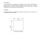
User Interface The Catalyst Monitor is configured via the keypad on the front panel which includes a graphical backlit LCD display capable of displaying alpha numeric values and custom engineering units of measure. The keypad implements a menu system, which is navigated using the up, down, left, right, enter and escape buttons. Installation: The Catalyst Monitor is a standard ¼ DIN package, designed to be panel mounted. The cutout dimensions are shown below.
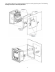
The Catalyst Monitor has integral mounting clips for securing into the panel. The following drawings illustrate the mounting procedure.
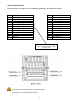
Terminal Connections All connections are made via the removable connectors on the back of the unit.
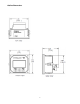
Outline Dimensions 7
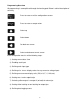
Programming Overview All programming is accomplished through the front keypad. Below is a brief description of each key. Press to enter or exit the configuration screens Press to enter or accept values Select up Select down Go back one screen Select and advance to next screen Initial configuration consists of the following steps: 1) Setting current date / time 2) Enabling each input 3) Defining each input type 4) Defining min. & max.
Programming Instructions Important: The Catalyst Monitor must first be programmed prior to operation. When initially powering up the unit, the display will first indicate the firmware version and then go to the operational mode. It may also display a screen warning that the time & date need to be entered. This will be explained below.
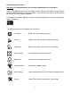
A description of each menu item follows: “Run Signal” There are (3) run types available. The definitions are as follows: None: No run indication required. Monitoring is always active. RPM: Monitoring is active when signal received from magnetic pickup. Digital: Monitoring is active when contact closure (connection to ground) is sensed. To select run signal type, use the up / down arrows to select, then press the right arrow to accept and advance to the next screen.
”Calibration” Select the channel number to configure by pressing the up / down arrows and pressing the right arrow to select and continue. The screens allow you to define the “Cal Zero” and “Cal Span” values for any channels that are configured for 0-1 V, 0-5 V, 0-10 V or 4-20 mA inputs. Example A pressure transmitter is connected to channel # 1. The transmitter has a 4-20 mA output representing a pressure input of 0 - 500 PSI.
“Communication” This allows configuration for downloading data and Modbus communications. ”Data Logging” The setup for EPA required logging of the catalyst inlet temperature based on a 4-hour rolling average is described in the section named “System” on page 14. Additional data logging may be configured when you select the “Data Logging” icon. The Catalyst Monitor can be configured to log any of the parameters being monitored, at user defined time intervals.
Select “A Value” on the next screen and press the arrow. On the following screen, select an RPM value that will indicate engine running. This value should be lower than the normal engine running speed and higher than the RPM defined as the “run” signal in page 9. The next screen will ask if you want to “Edit Another?” Select “yes” and press the Select “Compare 2” on the next screen and press the Select “RPM” on the next screen and press the arrow. arrow. arrow.
Pressing the escape key two times will escape to the normal monitoring mode. “System” “Display defaults” allows the selection of either single channel (absolute) or differential value display. Note that regardless of this setting, pressing the right or left arrow during normal operation will display the alternate display type.
Alarm Outputs The Catalyst Monitor will alarm when channel values or differential values are above or below limits as specified. Alarms can be configured as either latching or non-latching. If an alarm condition is met, the red LED on the front panel will blink and the digital output(s) will trip. The alarm point name (ch1, ch2, df1, df2) that caused the alarm will be stored in memory with date/time stamp info. Non-latching alarms will reset the alarm if its value returns to normal.
Downloading logged values to PC using LogReader software The hardware connection from the Catalyst Monitor to a PC is via a USB cable assembly, Dynalco p/n 270A-13020. The 6 ft cable length allows easy connection via a 4 pin Phoenix plug to the lower connector (terminals 5, 6, 7, 8) on the back of the Catalyst Monitor. When initially plugging the download cable into the PC’s USB port, the new device should be recognized and the driver installed automatically.
There are (3) reports generated by the LogReader software: The report named “CatalystDataLog” is a spreadsheet of logged values as configured in the Data Logging module (see page 12). This report does not contain 4-hour averaged values but only other events (up to 10 events) that may have been configured. An example of this download is below. Note that in this example, the columns format was selected which lines up the various log events (5 events in this case) in separate columns.
The 2nd report named “CatalystDataLogEPAInstant” contains the instantaneous catalyst inlet temperatures taken at 15 minute intervals. Note that the input channel configured to monitor the inlet temperature must also be configured as the “EPA Enabled” channel (see page 14). There are (4) different events that are assigned to the EPA enabled channel; events 21, 22, 23 & 24. The (4) temperature values in each event ID are then used to calculate one-hour averages.
Modbus Communication The unit also provides access to the internal registered values using the Modbus Protocol. The diagram below shows the recommended connections to the removable connectors on the back of the unit for either half-duplex or full-duplex (RS485). Wiring is as follows: PIN 5 6 7 8 Description TD(A) ** TD(B) ** Jumper to PIN 5 Jumper to PIN 6 ** A 120 ohm termination resistor may need to be installed across pins 5 & 6.
Modbus Address Registers: The Modbus address registers are defined in the tables below. Input Register Table (table 1) Modicon Address Modbus Offset Description 300001 0 300002 1 Status Register, 0=not running, 1=running.
300017 16 Channel 5 High Alarm Limit -32768 32767 16 bit signed integer 300018 17 Channel 6 High Alarm Limit -32768 32767 16 bit signed integer 330019 18 -32768 32767 16 bit signed integer 300020 19 -32768 32767 16 bit signed integer 300021 20 -32768 32767 16 bit signed integer 300022 21 Channel 1 and 2 Differential High Alarm Limit Channel 3 and 4 Differential High Alarm Limit Channel 5 and 6 Differential High Alarm Limit Channel 1 Low Alarm Limit -32768 32767 16 bit signed
301046301049 10451048 Log Buffer Entry #12 Custom (See table 4) 301050301053 10491052 Log Buffer Entry #13 Custom (See table 4) 301054301057 10531056 Log Buffer Entry #14 Custom (See table 4) 301058301061 10571060 Log Buffer Entry #15 Custom (See table 4) 301062301065 10611064 Log Buffer Entry #16 Custom (See table 4) 301066301069 10651068 Log Buffer Entry #17 Custom (See table 4) 301070301073 10691072 Log Buffer Entry #18 Custom (See table 4) 301074301077 10731076 Log Buffer E
302006302007 20052006 Channel 3 Float Value -9999.0 99999.0 32 bit Float(IEEE 754) 302008302009 20072008 Channel 4 Float Value -9999.0 99999.0 32 bit Float(IEEE 754) 302010302011 20092010 Channel 5 Float Value -9999.0 99999.0 32 bit Float(IEEE 754) 302012302013 20112012 Channel 6 Float Value -9999.0 99999.0 32 bit Float(IEEE 754) 302014302015 20132014 Channel 1 and 2 Differential Value -9999.0 99999.
302048302049 20472048 Channel 6 High Low Limit -9999.0 99999.0 32 bit Float(IEEE 754) 302050302051 20492050 Channel 1 and 2 Differential Low Alarm Limit -9999.0 99999.0 32 bit Float(IEEE 754) 302052302053 20512052 Channel 3 and 4 Differential Low Alarm Limit -9999.0 99999.0 32 bit Float(IEEE 754) 302054302055 20532054 Channel 5 and 6 Differential Low Alarm Limit -9999.0 99999.0 32 bit Float(IEEE 754) 302056302057 20552056 RPM 0 99999.
25