3690 N.W. 53rd Street Fort Lauderdale, FL 33309 FWG-1200 Flywheel Generator Installation and Operation Manual Rev. 1.
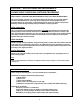
CAUTION!! – SPECIAL HANDLING REQUIREMENTS PLEASE READ THOROUGHLY BEFORE PROCEEDING THIS PRODUCT CONTAINS RARE EARTH MAGNETS THAT CAN CAUSE SEVERE INJURY! The rotor assembly consists of (2) rotor halves. Each rotor half has (18) rare earth magnets which are embedded into the outer ring. These magnets have extremely high attraction properties which can cause injury if not handled properly. Please use extreme caution when handling, whether during initial unpacking, installation or during operation.
System Overview The FWG-1200 Flywheel Generator System is designed to provide power to medium and high speed industrial engines. There are no wearing parts because there are no bearings, shafts, or couplings. The FWG-1200 can simultaneously power other products including engine shutdown panel, air/fuel ratio controls, and other auxiliary components. The FWG-1200 is CSA approved for Class I, Division 2, Groups A, B, C & D hazardous locations.
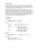
FWG-1200 System Installation: The FWG-1200 system is designed to fit almost any standard industrial engine given the proper space for all components. The three subassemblies shown above can be mounted to existing engine components or modified to meet user requirements. The following instructions describe the mounting procedures for each of the three subassemblies. Rotor Assembly: The Rotor Assembly consists of (2) halves that are to be mounted to the engine flywheel.
Terminal Connections Wiring: Power Coil: The (4) wires on the power coil are color coded and must be connected to the 4terminal block (J1) of the Power Supply Module as indicated. The wiring between the Power Coil and Power Supply Module must be run in conduit for protection. Power Supply Module: The 12 VDC output from the Power Supply Module is available from (2) outputs. The “Main” output provides up to 6 Amps output for powering the engine panel as well as providing charging current to the battery.
Important - Before Starting Engine: The “Main” and “Ignition” outputs are separate outputs that must be kept isolated. The (2) outputs must not be tied together. The “Ignition” output must be used for ignition only. The “Main” output must be connected to the battery (if applicable) and panel power. If the existing alternator system is left in place, it must be disconnected from the electrical system.
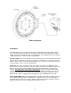
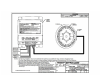
Outline Drawing – Power Supply Module 8