SWT-1000 Speed Switch / Transmitter Operating Manual rd 3690 NW 53 Street • Fort Lauderdale, FL 33309 • Ph 954-739-4300 • Fax 954-486-4968 • www.dynalco.
TABLE OF CONTENTS 1. 2. 2.1 2.2 2.2.1 2.2.2 2.2.3 2.3 2.3.1 2.3.2 2.3.3 2.4 2.4.1 2.5 2.5.1 3. 3.1 3.2 4. 5. 6. 6.1 6.2 7. 7.1 7.2 7.3 7.3.1 7.3.2 7.4 7.5 7.5.1 7.5.2 7.5.3 7.5.4 7.5.5 8. 8.1 8.1.1 8.1.2 8.2 8.2.1 8.2.2 8.3 8.3.1 8.3.2 8.3.3 8.3.4 8.3.5 8.4 8.4.1 8.4.2 8.4.3 8.5 9. 10. 11.
Operating Instructions SWT-1000 DYNALCO 1. Product Features The model SWT-1000 speed switch / transmitter measures and monitors frequencies (speed proportional values) in the range 0 to 35,000 Hz. The following are available: • 1 Current output • 1 Sensor frequency output • 1 Relay • 2 Limits • 2 Parameter sets – selectable via binary input • Sensor monitoring • System monitoring The tachometers are configured via SWT-1000 PC configuration software. All settings are in revolutions per minute (RPM).
Operating Instructions SWT-1000 DYNALCO 2. Specifications 2.1 General SWT-1000 Lowest measuring range Highest measuring range Minimum response time (Fix Time) Effective Measuring time 0.01 . . . 1.000 Hz 0.01 . . . 35.00 KHz Selectable values: 2 / 5 / 10 / 20 / 50 / 100 / 200 / 500 ms 1 / 2 / 5 Seconds. Is based on the minimum measuring time (Fix Time) and the measured frequency.
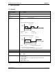
Operating Instructions SWT-1000 DYNALCO 2.2 Inputs 2.2.1 Analog Sensor Connection (Sign) Frequency range (-3dB) Input impedance Input voltage 0.01 Hz / 35 kHz 30kOhm • Max. 80Vrms • Max. frequency against input voltage 100 Input voltage [Veff] 10 O.K. 1 NOT O.K. 0.1 Trigger: 500mVpp Trigger: 20mVeff Frequency [Hz] Minimum positive pulse width - digital signals Input voltage Sensor supply Integrated pull-up Signal voltage [Vpp] Min. Pulse width [µs] 0.
Operating Instructions SWT-1000 DYNALCO 2.2.2 Digital Sensor Connection (IQ) Frequency range (-3dB) Input impedance Input voltage Minimum pulse width Sensor supply Trigger level Screen Sensor monitoring 0.01 Hz / 35 kHz 46 K Max. ± 36V peek Min. pulse width 1.5 µs +14 V, max. 35 mA short circuit proof. If the current limit activates, the sensor supply must be disconnected to reset the protection. • min.Ulow = 1.6 V • max.Uhigh= 4.5 V A terminal is provided for the sensor cable screen.
Operating Instructions SWT-1000 DYNALCO 2.3 Outputs 2.3.1 Analog Output Type Load Open circuit voltage Operating Mode SWT-1000 Current 0…20 / 4…20mA Max. 500 ohms Max. 12V [mA] 21 20 4...20mA mode 12 (minimal measured value) 4 0...20mA mode 0 initial value Transfer functions final value Normal or Inverse (rising or falling characteristic) output „normal“ output „invers“ speed Resolution Max Linear error Accuracy Damping Temperature Drift Reaction time SWT-1000.r2.
Operating Instructions SWT-1000 DYNALCO 2.3.2 Relay Type Limit Hysteresis Functions Accuracy Temperature tolerance Reaction time Contact rating Single Pole Double Throw Programmable – 1 lower and 1 upper set point per limit. 2 programmable parameter sets selectable via binary input • Reaction to Alarm, Sensor fault, Limit, always on or off. • “Normal“ or “Inverse“ (normally de-energized or energized) • With or without ‘Hold function’ (Reset via Binary input) 0.05% of the value set Max.
Operating Instructions SWT-1000 DYNALCO 3. Principle of Operation 3.1 General The SWT-1000 is controlled by a microprocessor. It works according to the period measurement principle whereby the input period is measured with subsequent computing of the reciprocal value corresponding to the frequency or speed. The relationship between frequency and speed is established with the Machine factor. The current output and relay control are determined from the speed.
Operating Instructions SWT-1000 DYNALCO 3.2 Machine factor The machine factor establishes the relationship between sensor frequency (Hz) and corresponding speed (RPM).
Operating Instructions SWT-1000 DYNALCO 4. Installation The SWT-1000 may only be installed by trained and competent personnel. An undamaged SWT1000, valid configuration and suitable installation are required. The power to the SWT-1000 should be capable of being disconnected via a switch or other emergency means. Before switching the equipment on, the power supply voltage should be verified to be in the permissible range.
Operating Instructions SWT-1000 DYNALCO 6. Hardware Configuration 6.1 Analog Sensor Input (Sign) J1 Jumper position 6.2 J1: Sensor type J2 J2: Adaptive trigger level range 2 wire sensors (with 820Ohm Pull Up resistance) 28mV to 6.5V (>20mVrms) 3 wire and electromagnetic sensors (factory setting) 250mV to 6.5V (>500mVpp) [factory setting] Digital Sensor Input (IQ) No hardware configuration necessary. SWT-1000.r2.
Operating Instructions SWT-1000 DYNALCO 7. Configuration with PC Software 7.1 Software Concept All settings are written via PC to the SWT-1000 using the RS232 interface and the aid of the user friendly menu driven SWT-1000 software. The parameter file may be stored, opened, printed and exchanged between the SWT-1000 and a PC. 7.2 PC Communications Communications with the SWT-1000 are initiated by the PC via the RS232 interface.
Operating Instructions SWT-1000 DYNALCO 7.4 Parameter List and Ranges If you already have a configuration file you can open and view it using the SWT-1000 Windows Software menu File Æ Open You can also connect the SWT-1000 to a PC (see section 7.2) and read back the parameters, SWT-1000 Æ Read parameters Once loaded into the software the parameter set may be printed via File Æ Print Normal Windows file handling rules apply. 7.
Operating Instructions SWT-1000 DYNALCO Warning: New configurations only become active after being downloaded into the SWT-1000 via: SWT-1000 Æ Write Parameters 7.5.1 System Parameters (Configuration Æ System) Machine Factor The machine factor establishes the relationship between sensor frequency and associated speed. Machine Factor = Frequency RPM See section 3.2 Machine factor. Once the correct machine factor is entered, all other settings e.g limits are made in RPM.
Operating Instructions SWT-1000 DYNALCO 7.5.3 Analog Output (Configuration Æ Analog Output) [mA] 21 20 4...20mA mode 12 (minimal measured value) 4 0...20mA mode 0 initial value final value speed [RPM] Measuring range – start value Analog output start value 0 or 4mA Measuring range – end value Analog output end value 20mA In the case of a negative transfer function the end value must be set smaller than the start value.
Operating Instructions SWT-1000 DYNALCO 7.5.4 Limits (Configuration Æ Limits) The SWT-1000 series offers 2 independent limits Æ Limit 1 and 2. Status Limits are selected here. If the limit is deactivated, the other values such as set points and mode have no further effect. Mode In Normal Mode the limit is active as soon as the High set point is exceeded.
Operating Instructions SWT-1000 SWT-1000.r2.
Operating Instructions SWT-1000 DYNALCO 8. Operating Behavior 8.1 Power On 8.1.1 Analog Output Following power on the output assumes the output range start value. Upon completion of the first measurement the output goes to the corresponding measured value. Relay Output The parameter set determined by the configuration and binary input is valid from the start.
Operating Instructions SWT-1000 DYNALCO 8.2.2 Signal Failure In the event of a sudden loss of a good signal, no positive edge arrives to complete the measurement or start a new one. Once the minimum measurement time (Fixtime) has lapsed the unit waits for twice the last measurement period following which half the last measured speed is assumed. If the signal remains missing then the measurement approaches zero. 8.3 Functions 8.3.
Operating Instructions SWT-1000 DYNALCO 8.3.5 Binary Input 2 functions are executable using the binary input: • Switching between parameter sets A and B. See 8.3.2 Parameter Sets A and B. • Resetting a latched relay. See 8.3.3 Rela. The binary input has an internal pull up resistor to +5V and is therefore normally logic High. 5 Volt Shorting the binary input to the sensor supply 0V creates a logic 0. Switching the input for between 0.1 and 0.
Operating Instructions SWT-1000 DYNALCO 8.5 Power Supply Interruption If input power remains off for longer than the permitted period the outputs deactivate i.e. the analog output goes to 0mA, the relay deactivates and the “open collector“ output becomes high resistance. Once the supply resumes in range the SWT-1000 begins its initialization routine. 9. Mechanical Construction / Housing The housing features front plugable terminals that are protected from accidental contact.