
User Manual


Operating Instructions SWT-1000 DYNALCO
SWT-1000.r2.0609 11
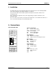
7. Configuration with PC Software
7.1 Software Concept
All settings are written via PC to the SWT-1000 using the RS232 interface and the aid of the user
friendly menu driven SWT-1000 software.
The parameter file may be stored, opened, printed and exchanged between the SWT-1000 and a
PC.
7.2 PC Communications
Communications with the SWT-1000 are initiated by the PC via the RS232 interface.
Prior to starting comms, Settings Æ Interface must be set to an appropriate serial interface.
The following settings also apply:
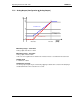
Transmission rate: 2400 Baud
Parity Bit: none
Data Bits: 8
Stop Bits: 2
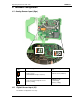
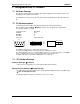
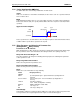
Connector: 3.5mm jack plug
2
3
5
TXD
RXD
GND
TXD RXDGND
5 1
9
6
female
The diagram shows the stereo jack plug to D9 connections.
The tachometer RXD must be connected to the PC’s TXD and vice versa.
The SWT-1000 does not use a standard RS232 signal (-5V…+5V) but operates at 5V CMOS
levels, compatible with most PC’s as long as the cable is not longer than 2m.
A suitable cable may be ordered from DYNALCO – see section 10.
7.3 PC Software Settings
Interface (Settings Æ Interface)
In this menu the serial interface for comms with the SWT-1000 is defined.
Display Interval (Settings Æ Display Interval)
The SWT-1000 measurement status may be interrogated and displayed on the PC via SWT-1000
Æ Start – Reading Measure Data.
The display update time may be set at intervals of ¼ to 10 seconds.