SWT-2000 Frequency Measurement and Switching Instrument Operating Manual 3690 NW 53rd Street • Fort Lauderdale, FL 33309 • Ph 954-739-4300 • Fax 954-486-4968 • www.dynalco.
TABLE OF CONTENTS 1. 2. 2.1 2.2 2.2.1 2.3 2.4 2.4.1 2.4.2 2.4.3 2.5 2.5.1 2.6 2.6.1 2.6.2 3. 3.1 3.2 4. 5. 5.1 5.1.1 5.1.2 5.1.3 6. 6.1 6.2 6.3 6.4 6.4.2 6.4.3 6.4.4 6.5 6.5.1 6.5.2 6.5.3 6.5.4 6.5.5 6.6 6.6.1 6.6.2 6.6.3 6.6.4 6.7 6.7.1 6.7.2 6.7.3 6.7.4 6.7.5 6.7.6 6.7.7 6.7.8 6.7.9 6.7.10 6.7.11 6.7.12 6.7.13 6.8 6.8.1 6.8.2 6.9 7. 7.1 7.1.1 7.1.2 7.1.3 7.2 7.2.
7.2.2 7.3 7.3.1 7.3.2 7.3.3 7.3.4 7.3.5 7.3.6 7.3.7 7.3.8 7.4 7.4.1 7.4.2 7.5 7.6 8. 8.2 9. Signal Failure Functions "FUNC" Push Button Parameter Sets A, B, C and D Limits Math Function Frequency X2 and X4 Relay and Open Collector Latch Function Analog Output Interpretation of System Limit Inputs Fault Behavior Sensor Error System Alarm Power Failure Behavior During Configuration Mechanical Construction / Housing Mounting Accessories Copyright © 2009 Dynalco. All rights reserved.
Operating Instructions SWT-2000 DYNALCO 1. Product Features The model SWT-2000 measures and monitors frequency signals (speed proportional values) in the range 0.025Hz to 50,000Hz. Available are: • 2 Frequency Inputs (Speed sensors) • 2 Analog outputs • 2 Binary input • 4 Relays • 2 Open Collector Outputs • 4 Parameter sets each having 6 System limits with 4 Limit values • Sensor monitoring • System monitoring The SWT-2000 is configured via Computer (PC) using resident operating software.
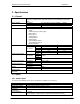
Operating Instructions SWT-2000 DYNALCO 2. Specifications 2.1 General Measurement time Supply voltage Isolation voltage Isolation Power consumption Power supply bridging 2ms / 5ms / 10ms / 20ms / 50ms / 100ms / 200ms / 500ms / 1s / 2s / 5s (Frequency measurements might take longer than the predefined measurement time) 90…264 VAC (47...
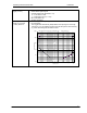
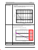
Operating Instructions SWT-2000 Max. Voltage: 80VRMS (226Vpp) Best suited to digital signals Schmitt Trigger Input (Hysteresis > 1V) „0“ = Low Level to 1.25V „1“ = High level from 3V (+/- 15%) Min. Pulse width: 5μs NO DC- decoupling Max. Voltage: 80VRMS (226Vpp) DC- decoupling The Trigger level automatically adapts itself to the input signal in the range +28.5mV to +2V. The Adaptive Trigger improves the signal to noise immunity e.g. where electromagnetic sensors are used. M in.
Operating Instructions SWT-2000 Input signal for adaptive trigger min. 500mVpp (+/-10%) 180mVRMS • • • DYNALCO Max. Voltage: 80VRMS (226Vpp) DC- decoupling The Trigger level automatically adapts itself to the input signal in the range +250mV to +2V. The Adaptive Trigger improves the signal to noise immunity e.g. where electromagnetic sensors are used. M in. T rigger level: 500 mVpp +/-10% = 180 mV RMS +/-10% U min. = f(Frequency) 1000.0 Sensor Signal (V pp) 100.0 O.K. 10.0 1.0 NOT O.K.
Operating Instructions SWT-2000 Sensor monitoring DYNALCO 3 sensor monitoring settings are available in the configuration software: • • No Sensor Monitoring Monitoring of supplied sensors (active Sensor Types) [Also for 2 wire sensors that are supplied via the internal Pull-up resistor (1kΩ) Æ Sensors drawing current outside of Imin or Imax are considered to be faulty. Imin = 0.5…35mA Imax = 0.
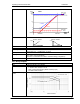
Operating Instructions SWT-2000 DYNALCO Mode [mA] Mode Failure level 0 … 20mA 21 20.5 20 12 4...20mA 0...20mA 4 Fehlerlevel 4 … 20mA 2 0 Startvalue Transfer Functions Startvalue < Endvalue Outputvalue Accuracy class Damping Temperature Drift Output Value Start value < or > End value Output Resolution Max. Linearity error Measuring error Endvalue Startvalue > Endvalue Output Outputvalue 14 Bit (16384 increments) 2 LSB (Least Significant Bit) ca. 2.7uA Max. 0.15 % f.m.v.
Operating Instructions SWT-2000 Reaction time Contact resistance Contact isolation DYNALCO Effective Measurement interval + max 6 ms 50 mΩ Max. (Initial contact) 1500 VAC (coil to contact) 1000 VAC (between open contacts) 2.4.3 Open Collector Outputs Number Type External resistance Reaction time Load voltage Isolation voltage Functions Inverting 2 Open Collector outputs Opto-coupler (passive) IC nominal = 15mA (RPull-up = V / I) Example: V = 24 V Æ R = 1.6 kΩ IC max.
Operating Instructions SWT-2000 DYNALCO 3. Principle of Operation 3.1 General The model SWT-2000 is microprocessor controlled and operates in accordance with the period measurement principle whereby the duration of the input period is measured during the measurement interval. The reciprocal value based on the average input period corresponds to frequency and hence speed. The relationship between frequency and speed is determined by the Machine Factor.
Operating Instructions SWT-2000 DYNALCO 4. Installation The SWT-2000 may only be installed by competent personnel. Only undamaged and correctly configured units may be used. Before switching on, check that the supply is within the permissible range. The Sensor cable screens must be connected terminals „Sh1“ and „Sh2“ respectively so as to minimize the effects of signal noise. These terminals are internally connected with 0V.
Operating Instructions SWT-2000 DYNALCO 5.1.
Operating Instructions SWT-2000 DYNALCO 5.1.
Operating Instructions SWT-2000 DYNALCO 6. Configuration via PC Software 6.1 Software Concept The SWT-2000 Ethernet connection is used to configure or interrogate the unit. (see Paragraph 9 Accessories) The resident menu driven configuration software is used for unit set up. Normal PC file handling procedures apply and the configuration file can be communicated between computer and SWT-2000. To run the Software you must have Java Runtime Environment (JRE) 1.5 or higher. 6.
Operating Instructions SWT-2000 DYNALCO 6.4 Configuration Software Configuration User and Process User SWT-2000 parameters are divided into 2 groups, Configuration and Process parameters. When the program is started, the window shows 3 log in levels, Config user, Process user or Guest. Process and Configuration users require passwords. As a Guest one only has the right to view measured data or print out actual parameters. A Process user can perform Guest functions and view and change Process parameters.
Operating Instructions SWT-2000 DYNALCO 6.5.2 …resetting to factory default To reset parameters to factory settings go to then click on OK. Note: If you have not saved the live parameters, they will be lost. 6.5.3 …loading To load an existing file go to , and select the required configuration file. Note: If you have not saved the live parameters, they will be lost. 6.5.
Operating Instructions SWT-2000 DYNALCO 6.6.3 Writing a Configuration to the SWT-2000 When a new configuration file is ready it can be downloaded into the tachometer. Go to , Enter. The new Parameters are then transferred to the Tachometer (can take 10s.). If no connection can be established this will be aborted after 3 attempts. Note: The actual file in the tachometer will be overwritten. 6.6.
Operating Instructions SWT-2000 DYNALCO 6.7.2 Binary Input Configuration To configure binary inputs go to , .
Operating Instructions SWT-2000 DYNALCO 6.7.5 Machine Factor Go to , . The Machine factor establishes the relationship between sensor frequency and associated machine speed. (see Paragraph 3.2 Machine factor) The Machine factor may also be set by means of the number of pulses per rev. The 2 parameters have a fixed relationship of factor 60 (Pulses per rev. = Machine factor x 60) Machine factor: Pulses per revolution: 0.0001 … 1 … 999,999 0.
Operating Instructions SWT-2000 DYNALCO 6.7.7 Math Function Go to ,
Operating Instructions SWT-2000 DYNALCO 6.7.8 System Limit Go to , . Every System Limit has the same 5 logic inputs: Sensor 1, Sensor 2, Math function, Binary input 1, Binary input 2. A hysteresis may be applied to the first 3. Each may be inverted or selected to form part of a logical combination or disabled. The logical combination of inputs may be OR or AND. Sensor alarm may be additionally combined OR with the System Limit result. Sensor 1: Limit low: Limit high: 0.
Operating Instructions SWT-2000 DYNALCO 6.7.9 Relay Outputs To configure relay outputs go to , . Relay configuration consists of: Assignment, the Latch Function and the Fail safe/Not fail safe mode.
Operating Instructions SWT-2000 DYNALCO Defines whether an Open Collector state should be held until reset. Safety Function Defines whether the Open Collector is to operate in Fail safe (deactivate at limit) or not fail safe mode (activate at limit). 6.7.11 Analog Output To configure Analog outputs go to , . 4 parameters are available: Assignment, Current range, Start and End values and the time constant.
Operating Instructions SWT-2000 DYNALCO 6.7.12 Copy Parameter Set Go to , . A Parameter set may only be copied from Parameter set A.
Operating Instructions SWT-2000 DYNALCO 6.8.2 Changing the Password Go to , or . Changing the password involves entering the old password and the new password twice. To save the password click on . The password is now stored in the configuration software. To change it in the SWT-2000 the data must be downloaded. A Configuration user may change the Process user password by entering the Configuration user password first.
Operating Instructions SWT-2000 DYNALCO 7. Operating Behavior 7.1 Power On The parameter set e.g. as defined by binary inputs is immediately valid. 7.1.1 Analog Output Immediately after power on, the output corresponds to the lower range value set. Following the first measurement interval the output corresponds to the measured value. 7.1.2 Relay Output Up until the first measurement interval is completed, all relays are de-energiZed. Thereafter they assume the defined condition.
Operating Instructions SWT-2000 DYNALCO 7.2 Frequency Measurement Every frequency measurement starts with the negative edge of the input signal. The last measured edge prior the end of the measurement interval completes the running measurement and immediately starts the next. An optimum measurement is achieved when the input period is shorter than the measurement interval.
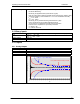
Operating Instructions SWT-2000 DYNALCO 7.2.2 Signal Failure Signal failure is defined as the sudden transition from an input frequency to no further recognisable pulses. The frequency is then calculated as follows: 1 n: the number of measurement intervals without an input signal f = tMeasuremen t × n The measured speed thereby follows an exponential function to the minimum frequency (0.025Hz) and then falls to zero. 7.3 Functions 7.3.
Operating Instructions SWT-2000 DYNALCO 7.3.4 Math Function To set a Math function on a speed input please follow the steps below. (Example for Sensor 1): 1. Set the Math function to S1. 2. 3. 4. 5. 6. Set Math function and Sensor 1 hysteresis. The Sensor – hysteresis gets the higher limit. Math function must be set to under run. All logic inputs must be switched off except Sensor 1 and Math function. The two inputs must be combined OR.
Operating Instructions SWT-2000 DYNALCO 7.3.5 Frequency X2 and X4 Prerequisites for the X2 and X4 function are that the input frequencies are synchronized, they exhibit approximately 90 degrees phase shift and a Mark : Space ratio of approximately 1:1. The X2 function is an EXOR combination of input frequencies S1 and S2. The X2 output frequency can reach a max value of 35KHz.
Operating Instructions SWT-2000 DYNALCO 7.3.8 Interpretation of System Limit Inputs Upper and lower set points may be set for each of the 3 system limit inputs. In this way a hysteresis is defined. If the upper set point is exceeded then this input assumes a status of 1. When the lower set point is then passed, the status returns to 0. If the actual value lies between the 2 set points then the status is as before.
Operating Instructions SWT-2000 DYNALCO 8. Mechanical Construction / Housing Dimensions 8.
Operating Instructions SWT-2000 DYNALCO 9. Accessories Interface Cable PC – SWT-2000 (6 Ft crossover): Part No.