
Manual

Operating Instructions SWT-2000 DYNALCO
15
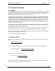
6.6.3 Writing a Configuration to the SWT-2000
When a new configuration file is ready it can be downloaded into the tachometer. Go to <Online>, <Write
Parameters> Enter. The new Parameters are then transferred to the Tachometer (can take 10s.). If no
connection can be established this will be aborted after 3 attempts.
Note: The actual file in the tachometer will be overwritten.
6.6.4 Compare Data
If you would like to compare a PC configuration file with that in the SWT-2000, first open the file and then go
to <Online>, <Compare Data>.
The actual file is then uploaded from the SWT-2000 and compared with the software parameters. A dialogue
window will then appear showing whether the files are identical or not.
6.7 Configuring
The factory defaults are written in bold.
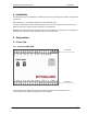
6.7.1 Speed Sensors
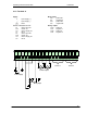
Go to <Configuration>, <Sensor>.
To connect the sensor see Paragraph 5 Connections.
5 Parameters are used to configure the sensor:
Type: powered / not powered
Resistor: activated / deactivated
Min. current: 0.5mA … 35mA
Max. current: 0.5mA … 35mA
Trigger level: fixed 3V / min 57mV
pp
/ min 500mV
pp
Sensor Type
Powered:
The sensor is supplied from the SWT-2000’s 14V (+/-0.5V) supply. To use static sensor
monitoring, the Min/Max current consumption must be defined.
Not powered:
The sensor is not powered by the SWT-2000 and no static monitoring is possible.
Internal pull up resistor
Deactivated:
The internal pull up is not in circuit.
Activated:
The internal pull up is in circuit.
Current monitoring
When the sensor is supplied from the tachometer upper and lower current limits must be entered. Current
consumption outside of the defined limits results in a static sensor error being signaled.
Trigger level
One of 3 modes may be selected. Fixed Trigger (fixed 3V) for digital sensors and two adaptive Triggers
(57 mV
pp
/ 500 mV
pp
) for Analog speed sensors (electromagnetic).