
Owner's manual


Operating Instructions SWTD-1000 DYNALCO
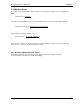
3//
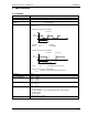
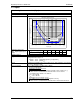
Max. frequency against input voltage
0.01
0.1
1
10
100
0.001
0.01
0.1
1
10
100
1000
10000
100000
Frequency [Hz]
Input voltage [Veff]
Trigger: 500mVpp
Trigger: 20mVeff
O.K.
NOT O.K.
3.2 Inputs
3.2.1 Analog Sensor connection (Sign)
Frequency range (-3dB) 0.01 Hz / 35 kHz
Input impedance 30 K
Input voltage
• Max. 80V
rms
•
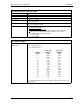
Signal voltage [V
pp
] 0.5 1 2.5 5 10 20
Min. pulse width [µs] 2000 667 333 200 166 125
Minimum positive pulse
width - digital signals Input
voltage
Integrated pull-up 820 Ohm to +V of the sensor supply (with Jumper J1)
Trigger level adaptive Trigger level.
Configurable with Jumper J2:
• 250mV … 6.5V (>500mVpp) [Factory configuration]
• 28mV … 6.5V (>20mV
rms
)
Screen A terminal is provided for the sensor cable screen. This terminal is connected to
the sensor supply 0V. (0VS)
Sensor monitoring 1 of 3 settings may be configured via software:
• No Sensor Monitoring
• Monitoring of powered sensors
[
Also for 2 wire sensors supplied via the Pull-up resistor (Jumper J1) ].
Æ The sensor is considered to be defective if the sensor current
consumption falls outside of I
min
and I
max
.
I
min.
= 0.5…25 mA
I
max.
= 0.5…25 mA
• Monitoring of non powered sensors
[
For 2 wire sensors such as electromagnetic sensors.]
Æ The sensor is considered to be defective if the circuit is disconnected.