
Instruction Manual

Standard Flash Head Features
¾ UV Color Corrected Flash Tube (2000 w/s part number 2405)
¾ Quartz Modeling Lamp (3200°K, 250 watts part number 0515)
¾ Universal Light Stand Mounting (for 1/2” and 5/8” light stands)
¾ Umbrella Mount (9mm hole accommodates up to 9mm umbrella’s)
¾ Protective Flash Head Cover
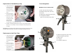
Setting up the MH2050 Flash Head
1. Unpack your new Dynalite flash head and make sure that all items are accounted
for in accordance with the parts designation list.
2. Before firing the flash head, be certain to remove the plastic flash head protective
cover (yellow cap).
3. Mount the flash head to an appropriately sized light stand and secure the flash
head to the light stand using the locking knob (see Parts Designation).
4. With the power pack OFF, connect the power pack cable to the head cable
socket (part number 0418) on the flash head. With the power pack OFF, connect
the other end of the power pack cord to the power pack socket. Ensure that both
connectors are securely fastened before turning the power pack ON.
Lighting Accessories
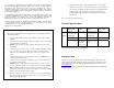
The new MH2050 flash head is compatible with the following lighting control accessories:
Catalog #
Description Catalog# Description
RR-50 10” 50° Parabolic Reflector RR-80 9” 80° Parabolic Reflector
RR-AR Angle Reducing Ring RR-AF Accessory Frame
RR-AFBD Barn Doors LR-716A Speed Ring
RR-GH 7” Grid Spot Holder LB-2432 24”x32” SM. Light bank
RR-4G 7” Black Grid Set LB-3648 36”x48” MED. Light bank
SR-65SN Snoot MGB-2432 24”x32” Grecco Light Bank
44-01B Umbrella MGB-3648 36”x48” Grecco Light Bank
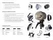
Dynalite Lighting Controls and System Accessories
RR-80
RR-50
RR-AR
MGB-2432 / MGB-3648
RR-GH
44-01B
RR-4G
SR-65SN
LR-716A
RR-AFBD