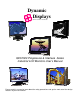
Dynamic Displays QUALITY EXCELLENCE SATISFACTION QES1500 Progressive & Interlace Series Industrial LCD Monitors User’s Manual Please read this manual to learn about the safety precautions and get the most out of the design features of your new monitor.
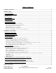
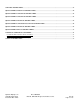
Table of Contents TABLE OF CONTENTS................................................................................................................................................................... 2 INTRODUCTION.............................................................................................................................................................................. 4 PRODUCT DESCRIPTION ......................................................................................................
CLEANING INSTRUCTIONS....................................................................................................................................................... 23 QES1508 SERIES 8.4-INCH LCD SPECIFICATION................................................................................................................. 24 QES1512 SERIES 12.1-INCH LCD SPECIFICATION............................................................................................................... 25 QES1514 SERIES 14.
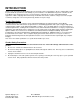
INTRODUCTION Thank you for purchasing the QES1500 Progressive & Interlace Series Color Monitor. We are confident that you will be pleased with the performance and reliability of your new monitor. The QES1500 Progressive & Interlace Series Color Monitor was designed to meet the screen performance requirements of today's demanding industrial applications.
MONITOR SETUP Unlike CRT displays, the LCD panel has a fixed pixel format over a set area. So for best performance, the “native resolution” setting is always recommended. Use the following notes as a reference to setup your display. • For 8.4” and 12.1” monitors: The native resolution of the LCD panel is 800 X 600; Recommended resolution is 800 X 600 @ 60 KHZ • For 14.1” and 15” monitors: The native resolution of the LCD panel is 1024 X 768; Recommended resolution is 1024 X 768.@ 60 KHZ • For 17”, 18.
Package Contents Before operating this monitor, please make sure that all items listed are present in your package: • LCD Monitor • AC/DC Adapter • AC Power Cord • VGA Cable • Users Manual - Download from WEB page Optional Items: These are optional items and can be ordered by contacting Dynamic Displays, Inc.
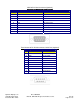
Signal Input Connections Following are the pin out descriptions for the standard and optional connectors provided on the monitor: VGA High Density HD15 Connector Pin Out Pin Assignments for VGA Video HD15 Input Connector PIN CONNECTION CONNECTION PIN 1 Red Video (75 Ohm, 0.7 Vpp) 9 Key (No pin) 2 Green Video (75 Ohm, 0.7 Vpp) 10 Sync Ground 3 Blue Video (75 Ohm, 0.
CGA 9 Pin D-Sub Connector (Optional) Pin Assignments for 9 Pin Optional CGA Color Graphics Adapter. Video Type: TTL PIN CONNECTION DESCRIPTION 1 GND Ground 2 GND Ground 3 R Red Video 4 G Green Video 5 B Blue Video 6 I Intensity 7 RES Reserved 8 HSYNC Horizontal Sync 9 VSYNC Vertical Sync EGA 9 Pin D-Sub Connector (Optional) Pin Assignments for 9 Pin Optional EGA=Enhanced Graphics Adapter.
MDA 9 Pin D-Sub Connector (Optional) Pin Assignments for 9 Pin Optional MGA – Hercules Mono Graphics Adapter. Video Type: TTL PIN CONNECTION DESCRIPTION 1 GND Ground 2 GND Ground 3 N/C No Connection 4 N/C No Connection 5 N/C No Connection 6 I Intensity 7 M Monochrome Video 8 HSYNC Horizontal Sync 9 VSYNC Vertical Sync Touch Screen 9 Pin D-Sub connector, Serial Port (Optional).
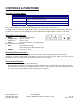
CONTROLS & FUNCTIONS Definitions of Video inputs: FUNCTION DESCRIPTION VGA / DVI Selects analog or digital input (Only works on DVI model option) Analog Input Select VGA input connector, HD15 Digital Input Select Digital Input Connector, DVI The monitor will NOT enter Auto Setup automatically the first time the unit is first turned on. The OSD interface is composed of 5 membrane switches (as shown below) and a Bi-color LED.
Definitions of PC and OSD Description Definition / Description / Function Definition: Personal Computer. Description: Generator image (Video Signal) on Flat Panel screen. PC Function: When in “PC Mode” the adjustments made will affect the Video Image on the screen with one exception, the Horizontal & Vertical Picture Size (This is done in OSD mode). Definition: On Screen Display. Description: Image (Menu) superimposed on a screen picture.
PC ADJUSTMENTS: Contrast Adjustment (Changes the contrast of the image): Press the “MENU” button to select “CONTRAST”. Use the “UP” / “DOWN” buttons to increase or decrease contrast. Select the “AUTO” button to exit contrast adjustment. Contrast Incremental Bar Brightness Adjustment (Changes the brightness of the image): Press the “MENU” button then the “DOWN” button to select “BRIGHTNESS”. Use the “UP” / “DOWN” buttons to increase or decrease brightness.
Color Mode adjustment (Changes the color of the image): Press the “MENU” button then the “DOWN” button to select “COLOR MODE”. Use the “MENU” buttons to select “NORMAL” / “WARM” / “COOL” / “sRGB” or “USER”. • Note: When selecting “USER” you may adjust each individual color one at a time. Use the “UP” / “DOWN” buttons to increase or decrease color. Select the “AUTO” button to exit color adjustment.
Clock adjustment (Changes the fine adjustment on the horizontal position of the video signals): Press the “MENU” button then the “DOWN” button to select “CLOCK”. Use the “UP” / “DOWN” buttons to increase or decrease clock adjustment. Select the “AUTO” button to exit clock position adjustment. Clock Incremental Bar Phase adjustment (Should be adjusted until the screen image is sharp): Press the “MENU” button then the “DOWN” button to select “PHASE”.
OSD ADJUSTMENTS With the On Screen Display (OSD) off, push the “MENU” button to display the main OSD menu. While the OSD is on, use the “UP” / “DOWN” buttons to select “OSD Menu”. Push “MENU” button to select “OSD Menu” option: OSD Menu Language adjustment (English Only): Press the “MENU” button to select “LANGUAGE” (English Only). Select the “AUTO” button to exit language adjustment.
Duration (Adjusts The timer to display the OSD menu): Press the “MENU” button then the “DOWN” button to select “DURATION”. Use the “UP” / “DOWN” buttons to increase or decrease the timer for the OSD display. Select the “AUTO” button to exit duration adjustment. Duration Incremental Bar OSD H-Position (During Alignment) Halftone (Adjusts Transparency of OSD menu): Press the “MENU” button then the “DOWN” button to select “HALFTONE”.
Memory Recall (Restores the image to the factory settings): Press the “MENU” button then the “DOWN” button to select “MEMORY RECALL”. Memory Recall Screen Adjust (Changes the horizontal and vertical size, aspect ratio or scaling factor of the image): Press the “MENU” button then the “DOWN” button to select “SCREEN ADJUST”.
HORIZONTAL SIZE: Press the “MENU” button then the “DOWN” button to select “H SIZE”. Use the “UP” / “DOWN” buttons to increase or decrease the Horizontal Size. The image width will change on the right side. Adjust to desired size. Once desired size is achieved you will have to adjust the “HORIZONTAL POSITION” to center the image. (See PC Adjustments, step #4) H. Size VERTICAL SIZE: Press the “MENU” button then the “DOWN” button to select “V SIZE”.
Test Your Saved Settings: Power the unit OFF and back ON using the POWER BUTTON on the keypad. The image should stay as you set it. Restoring Video Input Select To Factory Setting: Return Flat Panel To PC Operation Once It Has Been Changed To DVI 1. Power up the Flat Panel Monitor without Video Input. 2. DVI will be displayed in the upper right hand corner of image. 3. Select the “UP” button until TV is displayed in the upper right hand corner of image. 4. Push the “MENU” button. 5.
Return Flat Panel To PC Operation Once It Has Been Changed To TV Input 1. Power up the Flat Panel Monitor without Video Input. 2. TV will be displayed in the upper right hand corner of image. 3. Push the “MENU” button. 4. Push “UP” button, selecting OSD mode. OSD MODE 4. Push “MENU” button to (Enter). 5. Push “UP” button, selecting MEMORY RECALL. MEMORY RECALL 6. Push the “MENU” button. THIS WILL RETURN YOU TO PC OPERATION. Plug in Video input to Flat Panel Monitor.
TROUBLESHOOTING LCD Pixel Statement - The LCD unit is produced with high-precision manufacturing techniques. Nevertheless, some pixels may occasionally misfire or appear as black or colored dots. This has no effect on the recorded image and does not constitute a malfunction. Normally a 17” SXGA (1280 X 1024) display has nearly 4 million sub-pixels. Industry standard specification allows 8 non-performing pixels on the LCD screen, which is only 0.0002% of the total sub-pixels.
Uneven Color / Color Too Dark / Dark Area Distorted / White Color Is Not White Use OSD Color Temperature Menu to adjust color setting. No Sound Check the audio signal cable connection between the computer and LCD monitor. Try pressing the “+MUTE” button to disable the volume Mute function. * Some models do not have speakers (sound) The Display Is Dark / Bright Or Saturated Verify video input levels are appropriate; 0.7VPP for Analog inputs or 5 VPP for TTL input video signal.
CLEANING INSTRUCTIONS • When cleaning, unplug the AC adapter from the LCD display and outlet for safety. • Lightly wipe dirt from the cabinet and LCD panel surface with a clean lint-free cloth soaked in a neutral cleaning solution. This removes dust and other particles that can scratch the screen • Treat the LCD panel with care. Do not rub the LCD panel surface with a rough item or hit it on the surface. Also, do not strongly press the LCD panel surface.
QES1508 Series 8.4-inch LCD Specification Size/Technology 8.4 inch SVGA Color TFT LCD Module Viewing Area 170.4 mm x 127.8 mm Pixel Pitch 0.213 mm x 0.
QES1512 Series 12.1-inch LCD Specification Size/Technology 12.1 inch SVGA Color TFT LCD Module Viewing Area 246.0 mm x 184.5 mm Pixel Pitch 0.3075 mm x 0.
QES1514 Series 14.1-inch LCD Specification Size/Technology 14.1 inch XGA Color TFT LCD Module Viewing Area 285.7 mm x 214.3 mm Pixel Pitch 0.279 mm x 0.
QES1515 Series 15-inch LCD Specification Tabletop Models All Other Models Size/Technology 15” TFT Active Matrix LCD 15” TFT Active Matrix LCD Viewing Area 304.128 mm x 228.096 mm 308.8 mm x 231.9 mm Pixel Pitch 0.297 mm x 0.
QES1518 Series 18.1-inch Grayscale LCD Specification Size/Technology 18.1 SXGA Monochrome TFT/LCD Module Viewing Area 359.0 mm x 287.2 mm Pixel Pitch 0.280 mm x 0.
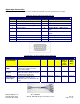
QES1519 Series 19-inch LCD Specification Size/Technology Viewing Area Pixel Pitch 19” TFT Active Matrix LCD 376.3 mm x 301.1 mm 0.294 mm x 0.294 mm Native Resolution 1280 x 1024 Pixels Back Light( Typical) 50,000 Hours Viewing Angle (H/V) 140°/130° Contrast Ratio (Typical) Brightness (Typical)) Response Time (Typical) Colors 600:1 250 Cd/m2 12 mSec 16.
QES1524 Series 24-In LCD Specifications Size/Technology 24.0” WUXGA Color TFT-LCD Viewing Area 518.4 (H) mm x 324 (V) mm Pixel Pitch 0.270 mm x 0.270 mm Back Light (Typical) 50,000 Hours Viewing Angle (H/V, Typical) 89° (Left), 89° (Right) / 89° (Up), 89° (Down) @ CR = 10 Contrast Ratio (Typical) 800:1 2 Brightness (Typical) 300 cd/m @ IL = 6 mA 2 270 cd/m @ IL = 6 mA with IntelliTouch SAW Touch Screen Response Time 16 mSec Typical, on/off; 6 mSec Average Colors 16.
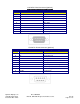
Universal Video Input Unit Option Dynamic Display’s unique Universal Video Input Option was designed to accept a wide variety of non-standard legacy video timing formats. It converts the signal to a VGA-style video format that is acceptable to most modern LCD displays. The Universal Video unit has a unique sync discriminator circuit that will filter out extraneous sync pulses found in some legacy video signals. The phase lock loop design supplies sync pulses that are missing in other legacy video formats.
• • D-SUB, 15HD (VGA) • D-SUB, 9HD (CGA / EGA) TTL • BNC (COMPOSITE / SYNC ON GREEN / SEPARATE SYNC / SEPARATE COMP. SYNC) After the correct input is determined set switch on (UVI) box for the correct input (D-SUB) or (BNC.) Switch located next to the last BNC on the right. Universal Video Input Box Specification: BNC Connector; 3/4/5 Wire RGB with Separate Sync, Composite Sync or Sync on Green.
Contact Information: Dynamic Displays, Inc 1625 Westgate Road Eau Claire, WI 54703 USA Phone: 800-793-6862 Fax: 715-835-2436 E-mail: sales@dynamicdisplay.com www.dynamicdisplay.com www.industrial-panels.