Dynamic Displays QUALITY EXCELLENCE SATISFACTION QES1500 Progressive & Interlace Units Industrial LCD Monitors User’s Manual Glee 17C2 Series
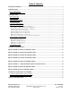
Table of Contents TABLE OF CONTENTS ............................................................................................................................................2 INTRODUCTION .......................................................................................................................................................3 PRODUCT DESCRIPTION ..............................................................................................................................................
Please read this manual to learn about the safety precautions and get the most out of the design features of your new monitor. INTRODUCTION Thank you for purchasing the QES1500 Progressive & Interlace Series Color Monitor. We are confident that you will be pleased with the performance and reliability of your new monitor. The QES1500 Progressive & Interlace Series Color Monitor was designed to meet the screen performance requirements of today's demanding industrial and military applications.
MONITOR SETUP Unlike CRT displays, the LCD panel has a fixed pixel format over a set area. So for best performance, the “native resolution” setting is always recommended. Use the following notes as a reference to setup your display. • 8.4”, 10.4” and 12.1” monitors: The native resolution of the LCD panel is 800 X 600; Recommended resolution is 800 X 600 @ 60 KHZ • 14.1” and 15” monitors: The native resolution of the LCD panel is 1024 X 768; Recommended resolution is 1024 X 768.@ 60 KHZ • 17”, 18.
Unpacking The Monitor Your LCD monitor package will consist of the following components listed on the section below. Open shipping container and lay all the components on a flat clean surface. If any component is missing, please contact Dynamic Displays as soon as possible. NOTES: • We recommend you to keep the packing box for transportation.
Connecting The Monitor No tools are required to install the LCD monitor. Simply follow the instructions outlined in the next few steps. Connectors for the signal and power are located on the back panel. • Connect Signal Cable (VGA): Attached the VGA cable connector with the ferrite bead closest to it to the graphics card adaptor on your computer system and attached the other end to the monitor. Be cautious in inserting the cable properly into both connectors.
Signal Input Connections Following are the pin out descriptions for the standard and optional connectors provided on the monitor: VGA High Density HD15 Connector Pin Out Pin Assignments for VGA Video HD15 Input Connector PIN CONNECTION PIN CONNECTION 1 Red Video (75 Ohm, 0.7 Vpp) 9 Key (No pin) 2 Green Video (75 Ohm, 0.7 Vpp) 10 Sync Ground 3 Blue Video (75 Ohm, 0.
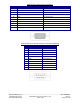
DVI (Digital Visual Interface) Connector Pin Out Pin Assignments for DVI Input Connector PIN CONNECTION PIN CONNECTION 1 TMDS Data 2− 16 Hot Plug detect TMDS Data 0− 2 TMDS Data 2+ 17 3 TMDS Data 2/4 Shield 18 TMDS Data 0+ 4 NC 19 TMDS Data 0/5 shield 5 NC 20 NC 6 DVI DDC SCL 21 NC 7 DVI DDC SDA 22 TMDS Clock Shield 8 Analog Vertical Sync 23 TMDS Clock+ 9 TMDS Data 1− 24 TMDS Clock− 10 TMDS Data 1+ C1 Analog Red 11 TMDS Data 1/3 Shield C2 Analog Green 12 NC C
CGA 9 Pin D-Sub Connector (Optional) Pin Assignments for 9 Pin Optional CGA Color Graphics Adapter. Video Type: TTL PIN CONNECTION DESCRIPTION 1 GND Ground 2 GND Ground 3 R Red Video 4 G Green Video 5 B Blue Video 6 I Intensity 7 RES Reserved 8 HSYNC Horizontal Sync 9 VSYNC Vertical Sync EGA 9 Pin D-Sub Connector (Optional) Pin Assignments for 9 Pin Optional EGA=Enhanced Graphics Adapter.
MDA 9 Pin D-Sub Connector (Optional) Pin Assignments for 9 Pin Optional MGA – Hercules Mono Graphics Adapter. Video Type: TTL PIN CONNECTION DESCRIPTION 1 GND Ground 2 GND Ground 3 N/C No Connection 4 N/C No Connection 5 N/C No Connection 6 I Intensity 7 M Monochrome Video 8 HSYNC Horizontal Sync 9 VSYNC Vertical Sync Touch Screen 9 Pin D-Sub connector, Serial Port (Optional).
OSD CONTROLS & FUNCTIONS The OSD interface is composed of 7 membrane switches (as shown below) and a Bi-color LED. All the adjustments required for the monitor are done through these buttons which interface with the Menu selections on the OSD. Menu Operating Instructions: Your LCD monitor allows you to easily adjust the characteristics of the image being displayed. All of these adjustments are made using the OSD control buttons on the front or rear of the monitor.
OSD Interface Controls; 1. PC/Picture (AV Mode) 1.1. Contrast; Increases or decreases video gain of the image. 1.2. Brightness; Increases or decreases the brightness of the image. 1.3. HUE; Only Available on S-Video or Composite Video. 1.4. Saturation; Only Available on S-Video or Composite Video. 1.5. Sharpness; Only Available on S-Video or Composite Video. 1.6.
1.9.5.4. High 1.9.6. MPEG NR - Only Available on S-Video or Composite Video. 1.9.6.1. Off 1.9.6.2. Low 1.9.6.3. High 2. SOUND 2.1. Equalizer 2.1.1. 120 Hz 2.1.2. 500 Hz 2.1.3. 1.5KHz 2.1.4. 5KHz 2.1.5. 10KHz 2.2. Balance; Sound balance Left and Right 2.3. Sound Mode 2.3.1. Standard 2.3.2. Movie 2.3.3. Music 2.3.4. User 2.4. AVC; Automatic Volume Control 2.4.1. Off 2.4.2. On 2.5. Surround 2.5.1. Off 2.5.2. On 3. SYSTEM 3.1.
3.1.1. English 3.1.2. Chinese 3.2. OSD H-Position; Adjust horizontal OSD positioning. 3.3. OSD V-Position; Adjust vertical OSD positioning. 3.4. OSD Duration; Adjust timer to display OSD. 3.5. OSD Halftone; In this function, user can adjust the transparency of OSD display. 3.5.1. Sleep – Timer; Turns of display image after a set period of no screen activity. 3.5.2. Off 3.5.3. 15 Min 3.5.4. 30 Min 3.5.5. 45 Min 3.5.6. 60 Min 3.6. Memory – Recall; Restore to factory settings. 3.7.
5.4. Phase; Phase adjustment; the phase should be adjusted until the screen image is sharp. 6. PIP – Picture in Picture 6.1. Multi Window 6.1.1. 6.1.2. PIP – Picture in Picture 6.1.3. POP – Picture Offset Picture 6.2. Sub Source 6.2.1. AV - Only Available on PC Mode. 6.2.2. S-Video - Only Available on PC Mode. 6.2.3. PC - Only Available on S-Video or Composite Video 6.2.4. DVI - Only Available on S-Video or Composite Video 6.3. Size – Only Available in PIP mode 6.3.1. Large 6.3.2.
TROUBLESHOOTING LCD Pixel Statement - The LCD unit is produced with high-precision manufacturing techniques. Nevertheless, some pixels may occasionally misfire or appear as black or colored dots. This has no effect on the recorded image and does not constitute a malfunction. Normally a 17” SXGA (1280 X 1024) display has nearly 4 million sub-pixels. Industry standard specification allows 8 non-performing pixels on the LCD screen, which is only 0.0002% of the total subpixels.
Uneven Color / Color Too Dark / Dark Area Distorted / White Color Is Not White Use OSD Color Temperature Menu to adjust color setting. No Sound Check the audio signal cable connection between the computer and LCD monitor. Try pressing the “+MUTE” button to disable the volume Mute function. * Some models do not have speakers (sound) The Display Is Dark / Bright Or Saturated Verify video input levels are appropriate; 0.7VPP for Analog inputs or 5 VPP for TTL input video signal.
CLEANING INSTRUCTIONS • When cleaning, unplug the AC adapter from the LCD display and outlet for safety. • Lightly wipe dirt from the cabinet and LCD panel surface with a clean lint-free cloth soaked in a neutral cleaning solution. This removes dust and other particles that can scratch the screen • Treat the LCD panel with care. Do not rub the LCD panel surface with a rough item or hit it on the surface. Also, do not strongly press the LCD panel surface.
QES1508 Series 8.4-inch LCD Specification Size/Technology 8.4 inch SVGA Color TFT LCD Module Viewing Area 170.4 mm x 127.8 mm Pixel Pitch 0.213 mm x 0.
QES1510 Series 12.1 inch LCD Specification 10.4” LCD Replacement for 12” CRT Monitor Size/Technology 10.4 inch SVGA Color TFT LCD Module Image Size 211.2 mm x 158.4 mm Pixel Pitch 0.264 mm x 0.
QES1512 Series 12.1-inch LCD Specification Size/Technology 12.1 inch SVGA Color TFT LCD Module with LED Backlight Viewing Area 246.0 mm x 184.5 mm Pixel Pitch 0.3075 mm x 0.3075 mm Native Resolution 800 x 600 Pixels LED Back Light 50,000 Hours Viewing Angle (H/V) 65°(Up) - 75°(Down) / 80°(Right) - 80°(Left) Contrast Ratio 700:1 Brightness 450 Cd/m2 Response Time 10 mSec Rising – 25 mSec Falling Colors 16.
QES1514 Series 14.1-inch LCD Specification Size/Technology 14.1 inch XGA Color TFT LCD Module Viewing Area 285.7 mm x 214.3 mm Pixel Pitch 0.279 mm x 0.
QES1515 Series 15-inch LCD Specification Tabletop Models All Other Models Size/Technology 15” TFT Active Matrix LCD 15” TFT Active Matrix LCD Viewing Area 304.128 mm x 228.096 mm Pixel Pitch Native Resolution 1024 x 768 Pixels Back Light 50,000 Hours Viewing Angle (H/V) 60° (Left), 60° (Right) / 40° (Up), 60° (Down) Contrast Ratio Brightness 400:1 350:1 250 Cd/m2 450 Cd/m2 Response Time Colors 308.8 mm x 231.9 mm 0.297 mm x 0.297 mm 16 mSec (Tr + Tf) 262K – (6 Bits for R, G, B) 16.
QES1517 Series - 17" Rugged Modular Flat Panel Display Size/Technology Viewing Area Pixel Pitch Native Resolution LED Life Viewing Angle (H/V Contrast Ratio Brightness Response Time Colors Supported Video Formats Standard Video Input Signals Sync Input Signal Input Interface (Connectors) Power Requirements Temperature Humidity Altitude - Operating Shock Cold Start-Up Vibration Drip Proof - Operating Fungus Salt Fog Sand Dust Crash Proof – Non Operating Rapid Decompression Safety Dimensions Warranty Op
QES1519 Series 19-inch LCD Specification Size/Technology Viewing Area Pixel Pitch Native Resolution Back Light Viewing Angle (H/V) Contrast Ratio Brightness Response Time Colors 19” TFT Active Matrix LCD 376.3 mm x 301.1 mm 0.294 mm x 0.294 mm 1280 x 1024 Pixels 50,000 Hours 140°/130° 600:1 250 Cd/m2 12 mSec 16.
QES1524 Series 24-In LCD Specifications Size/Technology Viewing Area Pixel Pitch Native Resolution Back Light Viewing Angle (H/V) Contrast Ratio Brightness Response Time Colors Supported Video Formats Video Input Signals Sync Input Signal Input Interface (Connectors) Power Requirements Agency Approvals Temperature: Operating Temperature: Storage Altitude: Operating Altitude: Storage Mechanical Configuration Dimensions Warranty 24.0” WUXGA Color TFT-LCD 518.4 (H) mm x 324 (V) mm 0.270 mm x 0.
Universal Video Input Unit Option Dynamic Display’s unique Universal Video Input Option was designed to accept a wide variety of nonstandard legacy video timing formats. It converts the video input signal to a VGA-style video format that is acceptable to most modern LCD displays. The Universal Video unit has a unique sync discriminator circuit that filters out extraneous sync pulses found in some legacy video signals.
• • Determine Video Plug input from your System: The (UVI) box supports D-SUB or BNC: • D-SUB, 15HD (VGA) • D-SUB, 9HD (CGA / EGA) TTL • BNC (COMPOSITE / SYNC ON GREEN / SEPARATE SYNC / SEPARATE COMP. SYNC) After the correct input is determined set switch on (UVI) box for the correct input (D-SUB) or (BNC.) Switch located next to the last BNC on the right. Universal Video Input Box Specification: BNC Connector; 3/4/5 Wire RGB with Separate Sync, Composite Sync or Sync on Green.
Contact Information: Dynamic Displays, Inc 1625 Westgate Road Eau Claire, WI 54703 USA Phone: 800-793-6862 Fax: 715-835-2436 E-mail: sales@dynamicdisplay.com www.dynamicdisplay.com www.industrial-panels.