DYNAMIX 2540 (FXO-04) VoIP Gateway User Guide
Contents CH1 Introduction ................................................................................... 4 1-1 Physical Interface ............................................................................. 4 1-2 IP Network connection.................................................................. 4 1-3 Environmental ................................................................................ 5 1-4 Front Panel: LED Indicators ..........................................................
5-1 SIP .................................................................................................. 35 5-2 Audio .............................................................................................. 37 5-3 Ring ................................................................................................ 38 CH6 Dialing Plan................................................................................. 40 6-1 General.........................................................................
Dynamix 2540 CH1 Introduction FXO-04 Telephony Gateway The Dynamix 2540 is a 4 ports FXO (Dynamix FXO-04) VoIP gateway which includes 1-WAN/1-LAN (management port) 10/100 base-T network environment. Field-proven quality of Voice communication and Fax transmission over IP broadband access network to makes Dynamix 2540 to be an excellent solution for various VoIP applications.
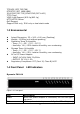
TCP/UDP (RFC 793/768) RTP/RTCP (RFC 1889/1890) IPV4 ICMP (RFC 792)/IPV6 ICMP (RFC 4443) TFTP Client VOIP VLAN Support (802.1q/802.1p) HTTP/HTTPS Server QoS Support Support IPV4 only, IPV6 only or dual stack mode 1-3 Environmental Actual Dimension: 35 × 242 × 160 mm (Desktop) Weight: 0.935kg (unit without packing) Operating Temp. & Humidity - Temp.: 0℃~45℃ (32℉~113℉) - Humidity: 10%~85% relative humidity, non-condensing Storage Temp. & Humidity - Temp.
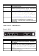
Proxy WAN LAN Line1~Line4 1-5 Rear Panel: green. When the gateway is registered successfully to a Proxy, this will light up green. This will light up green when the gateway’s WAN port is physically connected to the public internet. When data is transmitted through this port, it will flash green. The default IP of WAN port is 10.1.1.3. This will light up green when the gateway’s LAN port is physically connected to a local network (Refer to Rear Panel section in page number for location of LAN port).
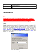
WAN AC100V~240V 10/100 Base-T RJ-45 socket for WAN port, connects to wide area network. The power socket, input AC 100V~240V, output DC 12V, 6A. 1-6 QUICK SETUP Note: Please use Windows XP IE 6.0 web browser or above version to configure FXO gateway webpage setting. Dynamix products don’t support other Web Browser such as FireFox to configure. Login : Setp1: Setup the administrative PC’s IP address to be same as Dynamix 2540 and connect the Ethernet cable into WAN or LAN port. Start IE6.
Step 2: After login, the screen shows the Home page of Dynamix FXO-04. (See figure 1-6-2 Network configure-1) Figure 1-6-2 Network configure-1 Change Default IP Network: Step 3: After successfully logon to the system, we need to change the network configuration. Click Device Setting > Network to setup the service network interface (WAN) parameters. Enter the deserved IP address, netmask and default gateway or selected to “DHCP” or “PPPOE”.
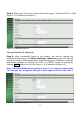
Change Default Time setting: Step 4: When re-logon to the new IP address, the next is to setup the system time zone. Click Device Setting > Time to setup the system. Enter the current SNTP server, time zone and daylight saving parameters. Apply the change by clicking Apply button. (See figure 1-6-4 Time setting) Figure 1-6-4 Time setting Modify SIP Account Parameter: Step 5: The next step is to add a SIP trunk for VOIP calling. For Dynamix 2540, it is necessary for VOIP calling .
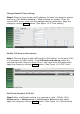
Figure 1-6-6 Quick-Reset Check Dynamix FXO-04 Registered Status: Step 7: After soft-reset or reboot. >Click Status > SIP Trunk Status to check whether registered or not. (See figure 1-6-7 SIP trunk status) Figure 1-6-7 SIP trunk status Through the above settings, the FXO-04 should able to do the following: For FXO (Dynamix 2540): 1. For PSTN incoming call, the caller will hear a dial tone. Then the caller can dial a VOIP number and it will use the setup SIP Trunk 1 to make SIP call out.
CH2 Device Settings From this setting category, all devices related parameters can be found here. 2-1 Network Configuration > Network Figure 2-1 network setting Parameter Description: Setting: IP Support: IP stack to be supported (IPV6 and IPV4 or IPV6 or IPV4 only) WAN Setting: Network Type: support “Fixed IP”;”DHCP”;”PPPOE” IP Address: IP address Default Gateway: Default gateway DHCP Tag (option 60): input Vendor class identifier or not.
WellGate 2540, Administrator can use LAN port instead. VOIP VLAN ID(2-4096): VLAN ID Used Note: the default WAN IP address is 10.1.1.3. LAN Setting: Management mode: This LAN port is used for management purpose, not used for register or routing. NAT mode: DHCP function on the LAN port. The LAN ports will function as a DHCP server, network devices connected to them will be issued with IP addresses.
2-2 Device Time Setting FXO-04 support SNTP with time zone and daylight saving. Device Setting > Time Figure 2-2 Time setting Parameter Description: Current Time: display time of now (display only) NTP Time Server: SNTP time server NTP Refresh Interval(sec): The frequency to sync NTP server in seconds Time Zone: The time-zone FXO-04 is located.
2-3 Device Advance Setting > Advance Figure 2-3 Advance setting Parameter Description: HTTP Service: The Administrator Web service port (the default is 80) HTTPS Service: The https web service port (the default is 443) Telnet Service: The telnet service port (the default is 23) HTTP/HTTPS Service access on WAN: When click the disable option; The WEB service will be rejected on WAN port, so please be careful with this function.
2-4 User Login Setting Three level of users can be used, administrator, supervisor, user. Each level of users will have different predefined access level. >User Login Figure 2-4 user login setting Parameter Description: Administrator: The administrator level user which has full access of Dynamix 2540 (FXO-04). Supervisor: The supervisor level user which has limited administrative access right. User: The user access right which only allows to setting some user related features.
2-5 Debug Settings Dynamix 2540 provides the real time debug to syslog or through telnet interface. It generates the debug information based on debug level and modules. Since the generating debug will consume system resource, it is recommended to turn on only for necessary and under Dynamix FAE’s instruction.
2-6 Event Notice FXO-04 1. 2. 3. 4.
2-7 Auto Provisioning The Dynamix 2540 can be provisioned by WellEMS 9510 for large deployment. Please contact Dynamix for availabilities. >Provisioning Figure 2-7-1 Provisioning Select 9510: Figure 2-7-2 Provisioning type of 9510 Parameter Description: (This function is not available yet for WellEMS 9510) EMS: Enable auto provisioning service by WellEMS 9510 or not. - Enable: Enable the service and use manual configured EMS server parameters. - Disable: Disable the auto provisioning service.
EMS IP address: The WellEMS 9510 server IP address EMS Server Port: The WellEMS 9510 Server port Data Encrypt: Disable: disable encryption function. Welltech encryption: Enable Welltech proprietary encryption for SIP signaling and RTP. It is required a Welltech SIP proxy server (WS6500 or SIPPBX 6200) to work with this feature. When enable it, you can hide your VOIP traffic from ISP’s monitor.
2-8 SNMP Figure 2-8 SNMP SNMP Agent: SNMP Agent: Enable SNMP or not. Read Only Community Name: The community name to read through SNMP protocol Read Write Community Name: The community name to read and write through SNMP protocol. SNMP Agent Access on WAN: Enable SNMP to be accessed through WAN port or not. Trusted Peer: Type: Any Address: Any address can retrieve the SNMP information. Specify an IP Address: Only the IP address listed can retrieve the SNMP information.
CH3 NAT Setting The Dynamix 2540 can support NAT, 2 ethernet leg (gw) or bridge mode. Here are the settings for NAT related service. 3-1 DHCP Ser. (DHCP server) Figure 3-1 DHCP server DHCP Server: Enable DHCP server or not. Client Range Start IP: specify DHCP client lease start IP Client Range End IP: specify DHCP client lease end IP Default Gateway: specify the default gateway Submask: specify the submask.
3-2 UPNP (universal plug and play server) Figure 3-2 UPnP UPNP IGD: Enable UPNP server or not. 3-3 Bandwidth (Bandwidth Control) By using bandwidth control feature, the user can manage the traffic based on their needs. Figure 3-3-1 Bandwidth control Bandwidth Control: Bandwidth Control: enable bandwidth control or not. Download Bandwidth: specify total bandwidth for download (unit: kbps). 0 indicates no limitation. Upload Bandwidth: specify total bandwidth for upload (unit: kbps).
Maximum Bandwidth and Reserved Bandwidth: Setup Method: bandwidth control method, percentage or specify the required bandwidth percentage : total bandwidth priority 1: highest priority percentage priority 2: Normal priority percentage priority 3: low priority percentage Figure 3-3-2 Bandwidth control specific : priority priority priority priority priority priority 1 2 3 1 2 3 – – – – – – Download: highest priority download bandwidth Download: normal priority download bandwidth
IP Target Figure 3-3-4 IP Target 1 Figure 3-3-5 IP Target 2 Priority: Priority value for the target Type: The target type is set to IP Configure Type: unique IP or a range of IP address Unique: IP Address: the IP address to be set IP Range: Start IP: The starting IP for a range End IP: The stopping IP for a range 24
Port Target Figure 3-3-6 Port Target Priority: Priority value for the target Type: The target type is set to port number Configure Type: unique port number or a range of port number Unique: Port: the port number to be added Protocol: protocol for the port Port Range: Start port: the starting port number End port: the stop port number Protocol: protocol for the port range Application Target Figure 3-3-7 Application Target Priority: Priority value for the target Type: Applicatio
DSCP target Figure 3-3-8 DSCP Target Priority: Priority value for the target Type: DSCP value DSCP: The DSCP will be mapped to the priority The FXO-04 support firewall features as below.
3-5 IP Filter Figure 3-5 IP Filter IP Filter: The specified IP address to be blocked Local IP address: The LAN side IP address to be forwarded Protocol: TCP, UDP or both are used for port forward 3-6 MAC Filter Figure 3-6 MAC Filter MAC Filter: The MAC address to be blocked 27
3-7 APP Filter Figure 3-7 App Filter APP Filter: application to be blocked 3-8 Port Filter Figure 3-8 Port Filter Port Filter: enable port Filter or not. Port Range: Starting and stopping port to be forward. If you are using only 1 port, please set the starting equal to stopping port. Protocol: TCP, UDP or both are used for port blocked.
3-9 Port Fwd The Dynamix 2540 (FXO-04) support port forward feature as below Figure 3-9 Port Fwd Port Fwd: enable port forward feature or not Port Range: Starting and stopping port to be forward. If you are using only 1 port, please set the starting equal to stopping port. Protocol: TCP, UDP or both are used for port forward Local IP address: The LAN side IP address to be forwarded Local Port: The LAN side port to be forwarded.
VOIP Parameters Setting SIP Parameters: CH4 VOIP Setting 4-1 SIP Figure 4-1 SIP setting Parameter Description: Session Timer: Enable session timer or not (RFC 4028) Session Expires (sec): This is the setting of initial session timer expires time according to RFC4028 - Session Timers in the Session Initiation Protocol. Min SE (sec): The minimum session timer allowed when receiving a call with session timer value according to RFC 4028.
4-2 Audio Figure 4-2 Audio setting Codec 1~5: The preferred codec priority G.711u Payload Size: G.711 u-Law payload size G.711a Payload Size: G.711 A-law payload size G.729 Payload Size: G.729A payload size G.723.1 Payload Size: G.723.1 payload size Bit Rate: G.723.1 bit rate used 5.3K bit rate is used 6.3K bit rate is used Codec Priority: Selection order to match the remote SDP for codec selection.
Enable: Start the voice activity (silence) detection when detect silence for 60 seconds, it will hang up the call. (For FXO use) Disable: Send silence packet as normal voice packet (no silence detection) RTP Basic Port: The RTP starting port. Each channel will be add additional 10. For example, the RTP basic port is 16384, thus call 1 will use 16384 while call 2 will use 16394 etc. RTP Qos Type: IP QoS tag for RTP stream DiffServ: The differentiated service QoS tag will be used.
4-3 Tone The setting page is used to setup the tone to be generated or detected. The detected tone is the Disconnect 1 & 2 (for FXO use) and the others are for generating (when FXS received the “bye” from IP side or waiting time out by analog phone which keeps handset pick up, it will send busy tone to analog phone). The disconnect tone is very important for PSTN status supervision. Figure 4-3 Tone setting Please use Country Template to select the country profile which will be applied.
4-4 NAT Traversal The Dynamix FXO-04 support the following NAT traversal methods Figure 4-4 NAT Traversal NAT Traversal: Disable: Disable NAT traversal features STUN (Type 1,2): Enable STUN for NAT traversal. Since STUN can be used only for type 1 and type 2 NAT server, it is recommended to use this option. When STUN client detect the used NAT is type 3 NAT, it will stop the STUN feature.
CH5 VOIP Advance 5-1 SIP Figure 5-1 SIP Parameter Description: SIP Hold Type: SIP on hold message sending method. - Send Only: Set the SDP media to sendonly when send an on-hold SIP message. - 0.0.0.0: Set the SDP connection to 0.0.0.0 when send an on-hold SIP message. - Inactive: Set the SDP media to inactive when send an on-hold SIP message. SIP Compact Form: Enable SIP compact form or not. When enable this feature, the connected SIP proxy is required to support compact form.
SIP T2 (msec): Determines the maximum retransmission interval as defined in RFC3261. For example, when an unreliable transport protocol is used, general requests are retransmitted at an interval which starts at T1 and doubles until reaches T2. If a provisional response is received, retransmission continue but at an interval of T2. (Default Value: 4000ms) ** SIP T4 (msec): T4 represents the amount of time the network takes to clear message between client and server transactions as defined in RFC3261.
will think the request is failed. The default is 5 seconds. Line Congestion Code: when callee's end system was contacted successfully but the callee is busy and does not wish to take the call at this time, the system wills response the code, default is 600. (FXO use) SIP-Info Flash Mode: when you enable the feature, system will make flash key to send SIP message by sip-info. 5-2 Audio The setting page includes the device related audio settings.
Min Jitter Buffer (msec): The minimum delay time of Jitter buffer. Max Jitter Buffer (msec): The Maximum delay time of Jitter buffer. Max Echo Tail Length (G.168): Enable the echo cancellation feature. The default setting is “128ms”. Jitter Opt. Factor: Jitter buffer dynamic factor for optimize. Please set to 7 unless under Dynamix’s instruction to change. Impedance: selected analog phone’s impedance.
(default is 20HZ) Ring on (0~8000ms): Specify the ringing on value (default is 1000msec) Ring off (0~8000ms): Specify the ringing off value (default is 2000msec) Ring level (10~95volt): Specify the ringing level (default is 94 volt) 39
CH6 Dialing Plan 6-1 General Figure 6-1 General setting First Digit Time Out: Specify the duration of dial waiting when the receiver is off hook. The range is 1~60 sec. Inter Digit Time Out: Specify the interval of input digits, if the interval is over the setting, the system will end the dial and send out the DTMF. The limitation range is 1~10sec. End of Digit: The assigned key will be tread as end of dial.
6-2 Dialing Rule Figure 6-2 Dialing Rule setting Dialing rule is used to speed up the dialing procedure. Some user don’t like to use the end of dialing digit such as “#”, the administrator can use dialing rule instead. The longest prefix will be matched first. Dialed Prefix: The prefix to be matched Max Digits: The digits will be received based on the Dialed Prefix.
6-3 Digit Manipulation The Digit Manipulation will be processed based on prefix and DM group after the DNIS is determined. Figure 6-3 Digit Manipulation setting DM Group: Different DM group have different case to be used. FXO: This DM group is used for FXO 2 stage dialing. After the DNIS is collected, this DM group will be processed before enter the routing procedure. VOIP: This DM group is used for VOIP incoming call.
6-4 Phone Book Phone Book is used for peer to peer call. Figure 6-4 Phone Book setting Name: This field supports called number only. If you enter words or text here, it will routes to proxy server automatically. Tel No: Enter called number and IP address. Please follow this sample of picture, as the format of “number@uri:port”. (default port is 5060) Export: To backup the phone book records. Import: To reload setting of phone book.
CH7 FXO Setting The FXO Setting contains the FXO related parameters. Figure 7-0 FXO setting Line ID: FXO line (L1 to L4) State: The line is active or not TEL No: The reference telephone number (e.g. PSTN TEL of line) Hotline TEL: If hot line is set, this field shows the hot line number. Export: backup all lines setting. Import: reload all line setting.
7-1 FXO line Figure 7-1 FXO setting User ID: FXO Line number (L1 to L4) User Type: the line type which is FXO Line State: Set to active if you would like to use this line. Otherwise, set to Inactive. TEL NO: This field can be used as a reference remark for this line. Normally, you can put the connected PSTN line’s phone number here for reference.
(Used for FXO port with 2-Stage Dialing Only ) Voice file name (MuLaw-mono 8K): Specify the file path and file name to u pload. Please make sure that the file format needs to be G.711U, 8K, 8 bits raw file. (Used for FXO port Only) Flash Time: Flash Time will be send to PSTN line (internal use only) FAX Relay: Enable T.
CH8 SIP Trunk The administrator needs to set the SIP trunk for VOIP outgoing call and incoming call. There are up to 4 SIP trunk can be used for whole system.
8-1 Create SIP Trunk Figure 8-1 SIP Trunk page Trunk ID: SIP trunk ID 1-4 Register Type: Whether this account need register or not Register: When it is set to r egister, Dynamix 2540 will send REGISTER message to SIP proxy server for registration. Predefine: When it is set to predefine, Dynamix 2540 will NOT send REGISTER message out.
SIP display name: The display name will be the Display Name set in this SIP trunk. FXO Tel NO: The display name will be the incoming FXO’s TEL No set on FXO lines. User ID: The SIP caller ID will be used according to th e following type. SIP user ID: If the SIP user ID is set, the SIP user ID set in this SIP trunk will be used and the domain/SIP proxy will be the host part. The SIP FROM header’s URL will be the SIP_User_ID@Domain or SIP_User_ID@SIP_Proxy_Server.
CH9 Route Plan The core of Dynamix FXO-04 is the routing policy. The policy is based on incoming call type/target, length and prefix to determinate the outgoing call process. For VOIP incoming call, it can send to FXO interface and vice versa.
9-1 Create Route Plan Click Route Plan and Click new to create a new routing policy. Figure 9-1 Route Plan setting Incoming Call Type: Incoming call type VOIP: The incoming SIP call type FXO: The PSTN incoming call type Matched Prefix: matched DNIS (called number) prefix Matched Incoming List: matched DNIS incoming interface target For VOIP incoming call type, the incoming target will be the SIP trunk ID. Only the call from the selected SIP Trunk will be accepted for this route.
basis. This is the recommended method. Routing List: The routing target list will be used for this route. DM Group: Select DM group 1 to 4 in case it requires an DM (for example remove the prefix) before to make the call. Create Route Plan>Backup Route Backup Route Active: Active the backup route or not. Outgoing Type: The backup route outgoing call type. Hunting Type: The hunting method will be used for this route. Please refer to the Primary Route.
CH10 Status Dynamix 2540 (FXO-04) provides the system status here.
10-2 Line States This page shows the each line’s current status.
10-3 SIP Trunk States Figure 10-3 SIP Trunk Status Account: SIP trunk account Registered: The SIP trunk register status Concurrent Call: The concurrent calls are used for this SIP trunk Refresh Interval (second): The time to refresh the status 55
CH11 Maintenance Dynamix 2540 can be managed by this management page for upgrading firmware or reset. Figure 11-0 Maintenance Backup: Backup the system settings for restoring purpose Restore: Restoring the backup setting back to Dynamix 2540 Reset to Default: Reset system setting to factory default Quick-Reset: Warm Reset without reboot Dynamix 2540 Reboot: reboot Dynamix 2540 11-1 Firmware Update This maintenance page provides the firmware upgrade features.
Appendix A --- System Recovery FXO-04 use dual firmware image to ensure the system stabilities. In most of case, you will not encounter the system failed to boot issue. Normally, the user should be able to use Web page to login and upgrade the firmware through it. If you are not able to do it, please follow the following steps for recovery. 1. 2. 3. 4. 5. Start the FXO-04 and to check the STATUS led is up or not. If STATUS led is ON, please press the reset button for 5 seconds to reset to default.
6. download the firmware into tftp data directory In the telnet terminal, do the following command 1. __dmctw 2. cd /config_fs 3. rm -f wg25*.bin 4. tftp –g –r wg25.1.0.bin 192.168.123.
7. 4. copy firmware successfully 5.
Appendix B --- HTTP auto provisioning Get the http provisioning packet from Welltech and start the provisioning as follows: Step 1: build mac list for mass configuration file generation For FXO> The Dynamix 2540 MAC.csv contains most frequently changed parameters as following: MACAddress: Dynamix 2540 MAC Address Siptk1.displayname ~ siptk4.displayname: display name for each line Siptk1.userid ~ siptk4.userid: user id for register to SIP proxy for each line siptk1.password ~ siptk4.
Step 5: Put the “*.cfg” file into http or ftp directory. Set the provisioning settings in Dynamix 2540 and reboot to test it. You can use the hfs for http file server. It can be download from http://www.rejetto.com/hfs/. Note: please link it to download provision file. More information please refers “wg2540 Parameter.txt”. http://www.welltech.com/support/voip2/SIP%20series/FXSO%20series/25x x/provision/2540/2540_Provision.
Appendix C--- Dynamix 2504 (FXS-04) and Dynamix 2540(FXO-04) in peer to peer mode with hotline by port to port application. Purpose This paper is going to describe how to configure FXO to FXS in peer to peer mode with hotline function to link from one desire port at FXO via SIP IP link to remote FXS desire port. This application is widely used to extend traditional PABX extension from one location to remote office via IP Link which could be VPN, Private network, fiber link or Wireless network.
Dynamix 2540 (4-FXO Gateway ) information : IP address : 192.168.23.23 SIP Line number : 1001, 1002, 1003 and 1004 FXO Telephone Number : default is Blank PABX Extension number 201, 202, 203 and 204 which were connected to Port #1 to #4 at FXO Gateway. Dynamix 2504 (FXS Gateway) configuration Step 1: Configure static IP address to Dynamix 2504, like below Figure 2. For example: Set static IP address of 192.168.18.201 at WAN port on Device Setting Network of Dynamix 2504 WEB page. Figure 2.
field to 1001 which is Dynamix 2540 FXO port 1 number. This command let FXS port #1 point to remote FXO port #1 directly. Continue to configure FXS port number 2 to 4 as following example at Modify Line Setting web page. See Figure 5. Enter HOT LINE TEL field to 1002 which is Dynamix 2540 FXO port 2 number. (This command let FXS port #2 point to remote FXO port #2 directly.) Enter HOT LINE TEL field to 1003 which is Dynamix 2540 FXO port 3 number.
FXS port 2 number 502 hotline to FXO SIP Trunk 2 which number is 1002, FXS port 3 number 503 hotline to FXO SIP Trunk 3 which number is 1003, FXS port 4 number 504 hotline to FXO SIP Trunk 4 which number is 1004, See Figure 4. Figure 4. Figure 5. Step 6: set the SIP Proxy information on FXS Setting SIP Proxy. See Figure 6. For example: Set the SIP Proxy Server’s IP address at 192.168.23.
Figure 6. Step 7: set Dynamix 2540 FXO number and IP address on FXS gateway’s webpage Dialing Plan Phone Book. See Figure 7. For example: the Dynamix 2540 FXO port 1 number is 1001, SIP local port is 8080. The FXS gateway’s phone Book format is as follows. FXO_line_number@FXO_ip_address:sip_port number. At this example, the FXS gateway phone book should configure four ports as follows. Port 1 configure to 1001@192.168.23.23:8080 Port 2 configure to 1002@192.168.23.23:8080 Port 3 configure to 1003@192.168.
Dynamix 2540 (FXO Gateway) configuration Step 1: set static IP address to Dynamix 2540 FXO gateway’s WAN port as following picture. See Figure 8. For example: Set static IP address 192.168.23.23 on Device Setting Network of Dynamix 2540 WEB page. Figure 8. Step 2: Go to VOIP Setting SIP to select the “Accept Proxy Only” feature to NO and make sure to setup the SIP Local Port number to 8080. See Figure 9. Figure 9. Step 3: Set the FXO SIP line’s information to each line.
FXO SIP port 2 number 1002 hotline to remote FXS port 2 number 502 directly. FXO SIP port 3 number 1003 hotline to remote FXS port 3 number 503 directly. FXO SIP port 4 number 1004 hotline to remote FXS port 4 number 504 directly. Figure 10. Step 4: Set the SIP Trunk information to Dynamix 2540 by going to SIP Trunk Modify SIP Trunk webpage. See Figure 11. 1. Select Register Type to Predefine and key in the Proxy Server IP address at 192.168.18.
User ID : 1003 User password: 1003 Display Name: 1003 Enter SIP Trunk #4 information as follows. TEL No : 1004 User ID : 1004 User password: 1004 Display Name: 1004 3. Select “2 Stage Dialing” at “DNIS is Register TEL” webpage. When user picks up the handset from FXS port #1 of Dynamix 2504, you should hear Dial Tone from PABX extension 201 which was connected to FXO Line #1. And it works like this analog phone was connected at remote PABX’s extension 201. See Figure 11.
Step 5: Set Route Plan to each FXO line. Disable the “VOIP Default Route” first. Figure 12. Set the Incoming Call Type to VOIP; Matched Prefix number from 1001 to 1004; Matched Length to 0 and Outgoing Type to FXO. See Figure 12. For example: Configure Route Plan to each line of FXO Gateway. a. Line #1 of FXO Gateway setting, see Figure 13. An FXS port 1 incoming call routes to FXO port 1 configuration example.
Figure 13. b. Line #2 of FXO Gateway setting, see Figure 14. An FXS port 2 incoming call routes to FXO port 2 configuration example. Incoming Call Type : VOIP Matched Prefix : 1002 Matched Length : 0 No Answer Timeout : 30 (MUST be longer than 10 seconds). Outgoing Type : FXO Hunting Type : selected anyone. Routing List : 01. Line 2 ; 02. None. ; 03. None ; 04. None. Figure 14. c. Line #3 of FXO Gateway setting, see Figure 15. An FXS port 3 incoming call routes to FXO port 3 configuration example.
Figure 15. d. Line #4 of FXO Gateway setting, see Figure 16. An FXS port 4 incoming call routes to FXO port 4 configuration example. Incoming Call Type : VOIP Matched Prefix : 1004 Matched Length : 0 No Answer Timeout : 30 (MUST be longer than 10 seconds). Outgoing Type : FXO Hunting Type : selected anyone. Routing List : 01. Line 4 ; 02. None. ; 03. None ; 04. None. Figure 16.
4. Configure incoming Ring Cadence to FXO Gateway When you connect Dynamix 2540 FXO gateway Lines to local PABX’s extension or PSTN switch, please go to Dynamix 2540 webpage setting at VOIP Advance Ring to configure proper Ring Cadence ( Ring ON time and Ring OFF time ) according to the PABX or PSTN ring Cadence specification. Without configuring Ring Cadence to FXO gateway properly according to PABX or PSTN Ring Cadence, FXO may detect Ring signal in a strange behavior and cause abnormal operation.
See Figure 18. Step 2: Go to FXO Gateway webpage configuration at SIP Trunk Modify SIP Trunk to enable Outgoing Caller ID with both Display Name: PSTN Caller ID and User ID: PSTN Caller ID as following Figure 19. After this configuration, FXO gateway send detected Caller ID signal from PABX or PSTN Lines to remote FXS gateway. There are additional two options at Display Name and User ID to select what number are going to send to remote FXS gateway. Here are summary of three options. a. b. c.
See figure 19. FXO Gateway Caller ID Mode. Figure 20. FXO Telephone Number. Step 3: Enable Caller ID generation at Dynamix 2504 FXS gateway. See Figure 21. Go to FXS Setting FXS Line Caller ID Mode to select Transparent to enable Caller ID generation. After enable this command, analog telephone set is able to display Caller ID either FXS phone number (at this example, they are 501 to 504) or display number which were sent from FXO gateway ( PSTN, SIP Trunk or FXO Line number).
Step 4: Select FXS gateway’s Caller ID Mode. See Figure 22 and 23. FXS Gateway Caller ID generation is able to configure which Caller ID mode in order to match analog phone set’s Caller ID specification. Go to FXS Setting Caller ID Caller ID Mode to select one of Caller ID Mode ( DTMF, FSK Bellcore, FSK ETSI, See Figure 23 ). There are other options you may need to pay attention at Polarity Reverse Before Caller ID, Dual Tone Before Caller ID, Caller ID Present, DTMF Caller ID start and stop digit.
Figure 23. Three options of Caller ID Mode.
6. Release FXO Line from PSTN or PABX extension after call was dropped. FXO analog interface detect disconnect tone which was sent from PABX extension or PSTN line to release tip/ring phone wire. In other word, the FXO line can only drop call after detect an effective disconnect tone. In FXO gateway webpage configuration, Go to VOIP Setting Tone to configure Disconnect 1 and Disconnect 2 in which disconnect tone are needed to match with PABX or PSTN disconnect tone. See figure 24.
Figure 25. Loop Current Drop to release FXO port Figure 26. Loop Current Drop detection Time.
7. FLASH command generation and detection on FXO and FXS gateway. FLASH feature is widely used for PABX extension to implement PABX’s advanced features such as Call Transfer, Call Hold, Conference, Forwarding or Call Park and others. PABX relies on extension’s analog phone set to generate Flash time to inform PABX this is an FLASH command. In this FXO+FXS P2P Hotline application, FXS needs to detect a FLASH command from analog phone set and transmit to FXO gateway via VoIP network.
Figure 28. Setup FXO Flash time generation.