Dynamix UM-SNB User Manual Version 1.
Tables of Contents 1. 2. INTRODUCTION .................................................................................................................................4 1.1 FEATURES ............................................................................................................................................. 5 1.2 SPECIFICATION ....................................................................................................................................... 5 1.3 APPLICATIONS.......
.7 4. SUB‐MENU TREE FOR DISGNOSTIC ....................................................................................................... 62 3.7.1. Loopback function ...................................................................................................................... 62 3.7.2. BER Test function ........................................................................................................................ 65 PARAMETERS TABLE..................................................
5. CONFIGURATION WITH CONSOLE PORT............................................................................................84 5.1 LOGIN PROCEDURE ............................................................................................................................... 84 5.2 WINDOW STRUCTURE ........................................................................................................................... 85 5.3 MAIN MENU SUMMARY ........................................................
1. Introduction The UM-SNB offers four different interfaces (E1,T1, Serial and Ethernet) connecting customers to high-speed TDM services. This series have 12 models as following:- E1 interface model (UM-SNB/E1 , UM-SNB/E1/4w): It offers two different ways to connect customers a high-speed TDM services with two G.703 E1 interfaces (Balanced 120Ω RJ45 jack and Unbalanced 75Ω dual BNCs). The G.703 interface will carry from 64kbps to 2.048Mbps.
flexibility is provided as the ability to manually set the maximum NTU speed at different levels for different customer-tailored service offerings. 1.1 Features y Standard G.SHDSL.Bis ITU G.991.
y Line code: B8ZS y Framing: SF/ESF/Unframed y Data Rate : 64kbps to 1.536Mbps ( N=1 to 24) y Operation : Clear Channel and Factional T1 Serial Interface (as RS-530/V.35/X.21) • Payload rates: Up to 5.696Mbps(for 2-wire model) or Up to 8.192Mbps(for 4-wire model) • Support V.35/RS-530 or V.36/X.
• Power Consumption: 10W Max • Operation temperature: 0 to 50°C • Humidity: Up to 95% (non-condensing) • External screw for frame grounding Products Information: Interface 2-wire 4-wire Single Interface E1 UM-SNB/E1 UM-SNB/E1/4w model Serial UM-SNB/35 UM-SNB/35/4w Ethernet UM-SNB/L UM-SNB/L/4w Multi E1+T1 UM-SNB/703 UM-SNB/703/4w Interface E1+Series+Ethernet UM-SNB/3in1 UM-SNB/3in1/4w model E1+T1+Serial+Ethernet UM-SNB/4in1 UM-SNB/4in1/4w Dynamix UM‐SNB User Manual Ver 1.
1.3 Applications Dynamix UM‐SNB User Manual Ver 1.
2. Getting to know about the UM-SNB NTU This chapter shows the front and rear panel and how to install the hardware.
2.1.3. Ethernet interface model 2.1.4. Multi-interfaces model Front panel can be separated into three parts: LCD display, LED indicator and Keypads. The LCD display can show the status and configuration of the device. The local management interface will be done by keypad with this LCD display. The purpose of the keypad is to configure the setting or function selection on this NTU. The following table describes the LEDs’ functions of the SHDSL.
SYN E1 Green ERR LPB V.35 Red Yellow TD Green RD Green ERR LINK ETH 100M Red Green Green COL Red Off Loopback is off. On E1 line is connected. Off E1 line is dropped. Blink There are error seconds. Off There is not any error second. On Loopback is on. Off Loopback is off. On Data transmit in V.35. Off No data transmit in V.35. On Data receive in V.35. Off No data reveive in V.35. Blink Error second occurs. Off No error second. On Data transmit in Ethernet.
2.2 2.2.1. Rear Panel E1/T1 Interface Model AC power input version The rear panel of this model is including power switch, AC power socket, RJ-45 console, G.703 RJ-48C jack or BNC jack for transmitting and receiving and RJ-45 for DSL cable from left to right. DC power input version The rear panel of this model is including power switch, DC power socket, RJ-45 console, G.703 RJ-48C jack or BNC jack for transmitting and receiving and RJ-45 for DSL cable from left to right.
Connector Description ON Power switch. Press 1 for turn on and press 0 for off 90~240V AC IEC-320 C6 AC input connector. It has power adapting function from 90V to 240V -48V DC power input connector (-48V) GND CONSOLE RJ-45 for system configuration and maintenance RJ-48C for 120Ω E1/T1 connection with PABX (Private Automatic Branch Exchange) or E1 G.703 Router TX BNC for 75Ω E1 transmitting RX BNC for 75Ω E1 receiving SHDSL RJ-45 for DSL connection Dynamix UM‐SNB User Manual Ver 1.
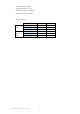
2.2.2. Serial Interface Model AC power input version The rear panel of this model is including power switch, AC power socket, RJ-45 for console cable, DB-25(Female) for serial cable and RJ-45 for DSL cable from left to right. DC power input version The rear panel of this model is including power switch, DC power socket, RJ-45 for console cable, DB-25(Female) for serial cable and RJ-45 for DSL cable from left to right.
2.2.3. Ethernet Interface Model AC power input version The rear panel of this model is including power switch, AC power socket, RJ-45 for console cable, LAN for Ethernet cable and RJ-45 for DSL cable from left to right. DC power input version The rear panel of this model is including power switch, DC power socket, RJ-45 for console cable, LAN for Ethernet cable and RJ-45 for DSL cable from left to right.
2.2.4. Multi-interfaces in one Model DC power input version The rear panel of this model is including power switch, AC power socket, RJ-45 for console cable, LAN for Ethernet cable, G.703 RJ-48C or BNC jacks for transmitting and receiving, DB-25(Female) for serial cable and RJ-45 for DSL cable from left to right. DC power input version The rear panel of this model is including power switch, DC power socket, RJ-45 for console cable, LAN for Ethernet cable, G.
Connector Description ON Power switch. Press 1 for turn on and press 0 for off 90~240V AC IEC-320 C6 AC input connector. It has power adapting function from 90V to 240V -48V DC power input connector (-48V) GND CONSOLE RJ-45 for system configuration and maintenance RJ-45 LAN port for Ethernet cable ETH RJ-48C for 120Ω E1/T1 connection with PABX (Private Automatic Branch Exchange) or E1 E1 Router SERIAL DB-25(F) for RS-530 and V.35 or X.
2.3 Installation Note: To avoid possible damage to this NTU, do not turn on the product before hardware installation. (a) Plug the power cord in the power socket. (b) Plug the console port in console if you want to configure the NTU with VT100 program of NB or PC. (c) Plug the E1/T1 cable ( 75Ω BNC cables for E1 or 120Ω cable for E1 or T1) or/and SERIAL cable or/and Ethernet cable (d) Plug SHDSL cable (e) Power on Dynamix UM‐SNB User Manual Ver 1.
2.3.1. E1/T1 Interface AC power input version DC power input version Dynamix UM‐SNB User Manual Ver 1.
AC & DC dual power input version (Use DC input only) Dynamix UM‐SNB User Manual Ver 1.
2.3.2. Serial Interface AC power input version DC power input version Dynamix UM‐SNB User Manual Ver 1.
AC & DC dual power input version (Use DC input only) Dynamix UM‐SNB User Manual Ver 1.
2.3.3. Ethernet Interface AC power input version DC power input version Dynamix UM‐SNB User Manual Ver 1.
AC & DC dual power input version (Use DC input only) Protective earth: The marked lug or terminal should be connected to the building protective earth bus. The function of protective earth does not serve the purpose of providing protection against electrical shock, but instead enhances surge suppression on the DSL lines for installations where suitable bonding facilities exist. We strongly recommend to grounding this device for lightning protection purpose. The connector type is M3 machine screw.
3. Configuration with Keypad and LCD This chapter provides information about the configuration of your UM-SNB NTU via front panel LCD display and keypads. 3.1 Keypad The UM-SNB is designed to provide an user-friendly configuration and management by using keypad and LCD display on the front panel without a computer with the VT100 terminal software connected. Key Pad Exit/Enter/+ Description Return to previous configuration menu. Skip to next configuration menu or configure this item.
3.2 Main menu Tree Model vs. Interface modes support (table 1): Model Interface modes support UM-SNB/E1 , UM-SNB/E1/4w E1 interface E1 interface model UM-SNB/703 , UM-SNB/703/4w E1 interface E1 + T1 interface model T1 interface UM-SNB/35 , UM-SNB/35/4w Serial interface (V.35 , X.21) Serial interface model UM-SNB/L , UM-SNB/L/4w Ethernet interface Ethernet interface model E1 interface UM-SNB/3in1 , UM-SNB/3in1/4w Serial interface (V.35 , X.
Model vs. Interface modes support (table 2): Interface E1 Model 2-wire 4-wire UM-SNB/ UM-SN E1 B/E1/4w T1 Serial Ethernet E1+Serial E1+Ethernet T1+Serial T1+Ethernet ● ● ● UM-SN UM-SNB/ B/703/4 ● ● 703 w UM-SNB/ UM-SN 35 B/35/4w UM-SNB/ UM-SN L B/L/4w ● ● UM-SN UM-SNB/ B/3in1/4 ● ● ● ● ● ● ● ● ● 3in1 w UM-SN UM-SNB/ B/4in1/4 ● ● 4in1 w Dynamix UM‐SNB User Manual Ver 1.
After turning on device, the LCD display will prompt G.SHDSL .BIS NTU. Press Enter to enter. There will display some sub-menus as following: Please notice that the Ethernet interface mode has not SYSTEM DIAGNOSTIC. For more detail on these sub-menus, please refer to each chapter. Dynamix UM‐SNB User Manual Ver 1.
3.3 Menu tree for SHOW STATUS You can check the status via LCD display. The SHOW STATUS menu tree is as following. For more detail on these sub-menus, please refer to following: Dynamix UM‐SNB User Manual Ver 1.
Dynamix UM‐SNB User Manual Ver 1.
3.4 Menu tree for SHOW STATISTICS The product can display two kinds of statistics data: (a) Current 15 minutes period and 96 previous 15-minutes periods of SHDSL performance. (b) Current 24 hour period and 7 previous 24-hours periods of SHDSL performance. SHDSL’s statistics data: SHDSL ES SES UAS LOSW If using the E1 interface mode, it can also show the E1 performance data. (c) Current 15 minutes period and 96 previous 15-minutes periods of E1 performance.
Model vs. Interface modes and statistics support: SHDSL Model Interface modes support statistics support E1 statistics support ES ,SES,UAS,LOSW ES,SES,UAS UM-SNB/E1 , UM-SNB/E1/4w E1 interface E1 interface model ● ● UM-SNB/703 , UM-SNB/703/4w E1 + T1 interface model E1 interface ● ● T1 interface ● UM-SNB/35 , UM-SNB/35/4w Serial interface model Serial interface (V.35 , X.21) ● UM-SNB/L , UM-SNB/L/4w Ethernet interface model Ethernet interface ● E1 interface ● Serial interface (V.
3.4.1. Show Statistic on E1 Interface Dynamix UM‐SNB User Manual Ver 1.
3.4.2. Show Statistic on Serial/Ethernet/T1 Interface Dynamix UM‐SNB User Manual Ver 1.
3.5 Menu tree for SYSTEM SETUP You can setup five interface modes via LCD display. Dynamix UM‐SNB User Manual Ver 1.
3.5.1.
3.5.2. Sub-Menu tree for SETUP E1 Interface SYSTEM SETUP Î SETUP E1 E1 parameter setting: E1 Items Setting PCM31 PCM31C Channel PCM30 PCM30C FULL Pass Through Code AIS Build Outs Dynamix UM‐SNB Off On HDB3 AMI On Off 120 ohms 75 ohms User Manual Ver 1.
Framer Setting: Framer Slot Number First Slot PCM31 FAS 1 to 31 1 to 31 PCM31C FAS+CRC4 1 to 31 1 to 31 PCM30 FAS+CAS 1 to 30 1 to 31 (can’t use 16) PCM30C FAS+CAS+CRC4 1 to 30 1 to 31 (can’t use 16) FULL UNFRAMED The table of number of time slot vs.
Annex A/B/F/G 27 1~4 26 1~5 25 1~6 24 1~7 23 1~8 22 1~9 21 1~10 20 1~11 19 1~12 18 1~13 17 1~14 16 1~15 15 1~15,17 14 1~15,17~18 13 1~15,17~19 12 1~15,17~20 11 1~15,17~21 10 1~15,17~22 9 1~15,17~23 8 1~15,17~24 7 1~15,17~25 6 1~15,17~26 5 1~15,17~27 4 1~15,17~28 3 1~15,17~29 2 1~15,17~30 1 1~15,17~31 Number of 1st slot 4-wire Channel slot FULL PCM31 PCM30 (UNFRAMED) ----- ----- PCM31C 30 1~2 28 1~4 26 1~6 24 1~8 22 1~10 20 1~12 18
22 1~9 20 1~11 18 1~13 16 1~15 14 1~15,17~18 12 1~15,17~20 10 1~15,17~22 8 1~15,17~24 6 1~15,17~26 4 1~15,17~28 2 1~15,17~30 Note: When SHDSL.bis using 2-pairs(4-wires), the time slot number can only use even number When E1 framer is PCM31C and PCM30C and set pass through ON, no fractional function can be use. Dynamix UM‐SNB User Manual Ver 1.
3.5.3. Sub-Menu tree for SETUP SERIAL Interface SYSTEM SETUP Î SETUP SERIAL Dynamix UM‐SNB User Manual Ver 1.
Serial interface control signals settings: Serial Items INTERFACE Setting V.35 X.21(RS-530) T1 mode Nx64K (Rate) 2-wires Nx64K mode 4-wires CLOCK RTS Annex A/B 1 ~ 36 Annex F/G 1 ~ 89 Annex A/B 2 ~ 72 (even number only) Annex F/G 2 ~ 128 (even number only) Normal Inverse On From DTE On CTS Off From RTS On DSR Off From DTR On DCD Off From DSL 0mS DELAY 1mS 2mS 3mS Note: When SHDSL.
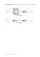
The handshake signal direction between DCE and DTE The below diagram shows CTS follow RTS, DSR follow DTR The RTS delay time is use to control CTS on delay to RTS signal, It works only for the setting: CTS follow RTS and RTS follow from DTE . Dynamix UM‐SNB User Manual Ver 1.
3.5.4. Sub-menu tree for SETUP Ethernet Interface SYSTEM SETUP Î SET UP ETHERNET If you set Ethernet Auto Negotiation as Enable, the default setting on Duplex is Full and Speed is 100M. If you set Ethernet Auto Negotiation as Enable, the Duplex and Speed cannot be set up and it will use auto configuration.
3.5.5. Sub-menu tree for SETUP T1 Interface SYSTEM SETUP Î SETUP T1 T1 parameter setting: T1 Items Setting SF Channel ESF Unframed Slot Number 1~24 First Slot 1 to (25 -Slot Number) 0 ~133ft 133 ~ 266ft LBO 266 ~399 ft 399 ft ~ 533ft 533ft ~ 655ft AIS Off On The T1 interface can encode/decode its transmit/receive signals using Bipolar with Eight Zero Suppression (B8ZS) coding. Dynamix UM‐SNB User Manual Ver 1.
The table of number of time slot vs.
3.5.6. Application of STU-R configuration follow STU-C Some configurations on STU-R side can follow STU-C side after DSL link up is finish. Such that on STU-R side, you do not care about the settings of the E1 channel/slot number/first slot, serial data rate or Ethernet data rate. When the DSL link up is finished, these configurations will follow the STU-C side.
3.5.7. Application of Multi-interface Dual interface vs.
PCM30 PCM30C Dynamix UM‐SNB 27 1 1~9 26 1 1~10 25 1 1~11 24 1 1~12 23 1 1~13 22 1 1~14 21 1 1~15 20 1 1~16 19 1 1~17 18 1 1~18 17 1 1~19 16 1 1~20 15 1 1~21 14 1 1~22 13 1 1~23 12 1 1~24 11 1 1~25 10 1 1~26 9 1 1~27 8 1 1~28 7 1 1~29 6 1 1~30 5 1 1~31 4 1 1~32 3 1 1~33 2 1 1~34 1 1 1~35 30 1 1~6 29 1 1~7 28 1 1~8 27 1 1~9 26 1 1~10 25 1 1~11 24 1 1~12 23 1 1~13 22 1 1~14 21 1 1~15 20 1 1~16 1
5 1 1~31 4 1 1~32 3 1 1~33 2 1 1~34 1 1 1~35 Annex F/G (2-wire) E1 interface Serial interface Ethernet interface Channel FULL PCM31 PCM30 Number of slot 1st slot Nx64K (Rate) (UNFRAMED) ----- ----- 1~57 PCM31C 31 1 1~58 30 1 1~59 29 1 1~60 28 1 1~61 27 1 1~62 26 1 1~63 25 1 1~64 24 1 1~65 23 1 1~66 22 1 1~67 21 1 1~68 20 1 1~69 19 1 1~70 18 1 1~71 17 1 1~72 16 1 1~73 15 1 1~74 14 1 1~75 13 1 1~76 12 1 1~77 11 1 1~78 10
20 1 1~69 19 1 1~70 18 1 1~71 17 1 1~72 16 1 1~73 15 1 1~74 14 1 1~75 13 1 1~76 12 1 1~77 11 1 1~78 10 1 1~79 9 1 1~80 8 1 1~81 7 1 1~82 6 1 1~83 5 1 1~84 4 1 1~85 3 1 1~86 2 1 1~87 1 1 1~88 Annex A /B (4-wires) E1 interface Serial interface Ethernet interface Channel Number of slot 1st slot Nx64K (Rate) FULL (UNFRAMED) ----- ----- 1~40 PCM31C 30 1 1~42 28 1 1~44 26 1 1~46 24 1 1~48 22 1 1~50 20 1 1~52 18 1 1~54 16
8 1 1~64 6 1 1~66 4 1 1~68 2 1 1~70 Annex F/G (4-wire) E1 interface Serial interface Ethernet interface Channel Number of slot 1st slot Nx64K (Rate) FULL (UNFRAMED) ----- ----- 1~96 PCM31C 30 1 1~98 28 1 1~100 26 1 1~102 24 1 1~104 22 1 1~106 20 1 1~108 18 1 1~110 16 1 1~112 14 1 1~114 12 1 1~116 10 1 1~118 8 1 1~120 6 1 1~122 4 1 1~124 2 1 1~126 30 1 1~98 28 1 1~100 26 1 1~102 24 1 1~104 22 1 1~106 20 1 1~108 18 1 1~11
Case 5 T1(Unframed)+ Serial interface Å---------Æ T1(Unframed)+ Serial interface Case 6 T1(Framed)+ Serial interface Å---------Æ T1(Framed)+ Serial interface Case 7 T1(Framed)+ Ethernet interface Å---------Æ T1(Framed)+ Ethernet interface Case 8 T1(Framed)+ Serial interface Å---------Æ T1(Framed)+ Ethernet interface Table of T1+ Serial interface or T1+Ethernet interface mode on both sides Annex A/B (2-wire) T1 interface Serial interface Ethernet interface Channel Number of slot 1st slot location
15 1 1~21 14 1 1~22 13 1 1~23 12 1 1~24 11 1 1~25 10 1 1~26 9 1 1~27 8 1 1~28 7 1 1~29 6 1 1~30 5 1 1~31 4 1 1~32 3 1 1~33 2 1 1~34 1 1 1~35 Annex G/F (2-wire) T1 interface Serial interface Ethernet interface Channel Number of slot 1st slot location Nx64K (Rate) range SF 24 1 1~65 ESF 23 1 1~66 22 1 1~67 21 1 1~68 20 1 1~69 19 1 1~70 18 1 1~71 17 1 1~72 16 1 1~73 15 1 1~74 14 1 1~75 13 1 1~76 12 1 1~77 11 1 1~78 1
20 1 1~52 18 1 1~54 16 1 1~56 14 1 1~58 12 1 1~60 10 1 1~62 8 1 1~64 6 1 1~66 4 1 1~68 2 1 1~70 Annex G/F (4-wire) T1 interface Serial interface Ethernet interface Channel Number of slot 1st slot location Unframed -- -- 1~104 SF 24 1 1~104 ESF 22 1 1~106 20 1 1~108 18 1 1~110 16 1 1~112 14 1 1~114 12 1 1~116 10 1 1~118 8 1 1~120 6 1 1~122 4 1 1~124 2 1 1~126 Dynamix UM‐SNB User Manual Ver 1.
Dual interface vs.
PCM30 PCM30C 5 1 1~26 4 1 1~27 3 1 1~28 2 1 1~29 1 1 1~30 29 1 1 28 1 1~2 27 1 1~3 26 1 1~4 25 1 1~5 24 1 1~6 23 1 1~7 22 1 1~8 21 1 1~9 20 1 1~10 19 1 1~11 18 1 1~12 17 1 1~13 16 1 1~14 15 1 1~15 14 1 1~16 13 1 1~17 12 1 1~18 11 1 1~19 10 1 1~20 9 1 1~21 8 1 1~22 7 1 1~23 6 1 1~24 5 1 1~25 4 1 1~26 3 1 1~27 2 1 1~28 1 1 1~29 Annex A /B/F/G (4-wires) E1 interface Serial interface Ethernet interface Chan
PCM30 PCM30C 17 1 1,3,5,7,9,11,13 16 1 2,4,6,8,10,12,14 15 1 1,3,5,7,9,11,13,15 14 1 2,4,6,8,10,12,14,16 13 1 1,3,5,7,9,11,13,15,17 12 1 2,4,6,8,10,12,14,16,18 11 1 1,3,5,7,9,11,13,15,17,19 10 1 2,4,6,8,10,12,14,16,18,20 9 1 1,3,5,7,9,11,13,15,17,19,21 8 1 2,4,6,8,10,12,14,16,18,20,22 7 1 1,3,5,7,9,11,13,15,17,19,21,23 6 1 2,4,6,8,10,12,14,16,18,20,22,24 5 1 1,3,5,7,9,11,13,15,17,19,21,23,25 4 1 2,4,6,8,10,12,14,16,18,20,22,24,26 3 1 1,3,5,7,9,11,13,15,17,19,21,
Case 11 T1(framed)+ Serial interface Å---------Æ T1(framed) Case 12 T1(framed)+Ethernet interface Å---------ÆT1(framed) Table of T1+ Serial interface to T1 interface and T1+Ethernet interface to T1 interface mode on both sides Annex A /B/F/G (2-wires) E1 interface Serial interface Ethernet interface Channel Number of slot 1st slot Nx64K (Rate) SF 23 1 1 ESF 22 1 1~2 21 1 1~3 20 1 1~4 19 1 1~5 18 1 1~6 17 1 1~7 16 1 1~8 15 1 1~9 14 1 1~10 13 1 1~11 12 1 1~12 1
Annex A /B/F/G (4-wires) T1 interface Serial interface Ethernet interface Channel Number of slot 1st slot Nx64K (Rate) SF 23 1 1 ESF 22 1 2 21 1 1,3 20 1 2,4 19 1 1,3,5 18 1 2,4,6 17 1 1,3,5,7 16 1 2,4,6,8 15 1 1,3,5,7,9 14 1 2,4,6,8,10 13 1 1,3,5,7,9,11 12 1 2,4,6,8,10,12 11 1 1,3,5,7,9,11,13 10 1 2,4,6,8,10,12,14 9 1 1,3,5,7,9,11,13,15 8 1 2,4,6,8,10,12,14,16 7 1 1,3,5,7,9,11,13,15,17 6 1 2,4,6,8,10,12,14,16,18 5 1 1,3,5,7,9,11,13,15,17,19 4
3.6 Sub-menu tree for REBOOT SYSTEM REBOOT SYSTEM -> * REBOOT * YES -> press ”ENTER” key Some settings request system reboot for the setting to take effect. Dynamix UM‐SNB User Manual Ver 1.
3.7 Sub-Menu tree for DISGNOSTIC 3.7.1. Loopback function SYSTEM DIAGNOSTIC Î DIAG LOOPBACK Note : there is no SYSTEM DIAGNOSTIC menu on the Ethernet Interface Model If the device hasn’t connected or it is under handshake, it will not support farend line, farend payload and V.54.
Dynamix UM‐SNB User Manual Ver 1.
Dynamix UM‐SNB User Manual Ver 1.
3.7.2. BER Test function SYSTEM DIAGNOSTIC Î DIAG BER TEST This is the internal Bit Error Rate Tester (BERT) for complete testing of local and remote modem and the link quality without any external test equipment. This built-in Bit Error Rate Test generator can generate a standard 2047 (211-1) test pattern. DIAG BER TEST *BERT 2047* RUN When the BERT doesn’t have Bit Errors, it shows zero. Otherwise, it will show some number counter.
4. Parameters Table There are many parameters tables for end user easily to write down all setting of devices before installing those on sites. 4.1 4.1.1.
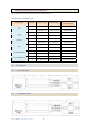
4.2 4.2.1. UM-SNB/35/ UM-SNB/35/4w UM-SNB/35/ UM-SNB/35/4w NTU SHDSL Serial Interface Model -- Serial interface mode Type □STU-R □STU-C-INTCLK Annex □A □F PSD □SYM SNR Margin (-10~21) Pair Mode □1 Pair Interface □V.35 Data Rate □Nx64K □B □G □ASYM □2 pair (For UM-SNB/35/4w only) □X.
4.3 4.3.1. UM-SNB/L / UM-SNB/L/4w UM-SNB/L / UM-SNB/L/4w NTU SHDSL Ethernet Interface model -- Ethernet interface mode Type □STU-R □STU-C-INTCLK Annex □A □F PSD □SYM SNR Margin (-10~21) Pair Mode □1 Pair □2 pair □Nx64K □T1 mode □B 1 Pair Date Rate 2 Pair Ethernet □STU-C-EXTCLK □G □ASYM (For UM-SNB/L/4w only) Annex A/B (1~36) Annex F/G (1~89) Annex A/B (2~72) Annex F/G (2~178) Auto Config □Disable □Enable Duplex □Full □Half Speed □100M □10M When SHDSL.
4.4 4.4.1.
4.4.2. UM-SNB/3in1 / UM-SNB/3in1/4w NTU SHDSL E1+Serial+Ethernet interface model -- Serial Interface mode ⊠Serial Interface □E1 Type □STU-R □STU-C-INTCLK Annex □A □F PSD □SYM SNR Margin (-10~21) Pair Mode □1 Pair Interface □V.35 □B □E1+Serial □E1+Ethernet □STU-C-EXTCLK □G □ASYM □2 pair (For UM-SNB/3in1/4w only) □X.
4.4.3.
4.4.4. UM-SNB/3in1 / UM-SNB/3in1/4w NTU SHDSL E1+Serial+Ethernet interface model -- E1+Serial Interface mode ⊠E1+Serial Interface □E1 Type □STU-R □STU-C-INTCLK Annex □A □F PSD □SYM SNR Margin (-10~21) Pair Mode □1 Pair □2 pair Channel □PCM31 □PCM31C □Serial □B □Ethernet □E1+Ethernet □STU-C-EXTCLK □G □ASYM (For UM-SNB/3in1/4w only) □PCM30 □PCM30C □Unframed Slot Number E1 First Slot Code □HDB3 AIS □Off □On Build Outs □75 Ohm □120 Ohm Interface □V.35 □X.
4.4.5.
4.5 4.5.1. UM-SNB/703/UM-SNB/703/4w UM-SNB/703 / UM-SNB/703/4w NTU SHDSL E1+T1 interface model -- E1 Interface mode Interface ⊠E1 Type □STU-R □STU-C-INTCLK Annex □A □F PSD □SYM SNR Margin (-10~21) Pair Mode □1 Pair □2 pair Channel □PCM31 □PCM31C Pass Through □Off □On □T1 □B □STU-C-EXTCLK □G □ASYM (For UM-SNB/4in1/4w only) □PCM30 □PCM30C □Unframed Slot Number E1 First Slot Code □HDB3 □AMI AIS □Off □On Build Outs □75 Ohm □120 Ohm When SHDSL.
4.5.2. UM-SNB/703 / UM-SNB/703/4w NTU SHDSL E1+T1 interface model -- T1 Interface mode ⊠T1 Interface □E1 Type □STU-R □STU-C-INTCLK Annex □A □F PSD □SYM SNR Margin (-10~21) Pair Mode □1 Pair Channel □SF □B □STU-C-EXTCLK □G □ASYM □2 pair □ESF (For UM-SNB/4in1/4w only) □Unframed Slot Number T1 First Slot LBO □0~133ft AIS □Off □133~266ft □266~399ft □399ft~533ft □On When SHDSL.
4.6 4.6.1.
4.6.2. UM-SNB/4in1 / UM-SNB/4in1/4w NTU SHDSL □E1 Interface ⊠T1 E1+T1 +Serial+ Ethernet interface model -- T1 Interface mode □Serial □Ethernet □T1+Serial □E1+Serial □T1+Ethernet Type □STU-R □STU-C-INTCLK Annex □A □F PSD □SYM SNR Margin (-10~21) Pair Mode □1 Pair Channel □SF □B □E1+Ethernet □STU-C-EXTCLK □G □ASYM □2 pair □ESF (For UM-SNB/4in1/4w only) □Unframed Slot Number T1 First Slot LBO □0~133ft AIS □Off □133~266ft □266~399ft □399ft~533ft □On When SHDSL.
4.6.3. UM-SNB/4in1 / UM-SNB/4in1/4w NTU SHDSL Interface E1+T1 +Serial+ Ethernet interface model -- Serial Interface mode □E1 ⊠Serial □T1 □T1+Serial □Ethernet □E1+Serial □T1+Ethernet Type □STU-R □STU-C-INTCLK Annex □A □F PSD □SYM SNR Margin (-10~21) Pair Mode □1 Pair Interface □V.35 □B □E1+Ethernet □STU-C-EXTCLK □G □ASYM □2 pair (For UM-SNB/4in1/4w only) □X.
4.6.4.
4.6.5.
4.6.6.
4.6.7. UM-SNB/4in1 / UM-SNB/4in1/4w E1+T1 +Serial+ Ethernet interface model -- T1+ Serial Interface mode NTU SHDSL Interface □E1 □Serial □Ethernet □T1 ⊠T1+Serial □E1+Serial □T1+Ethernet Type □STU-R □STU-C-INTCLK Annex □A □F PSD □SYM SNR Margin (-10~21) Pair Mode □1 Pair Channel □SF □B □E1+Ethernet □STU-C-EXTCLK □G □ASYM □2 pair □ESF (For UM-SNB/4in1/4w only) □Unframed Slot Number T1 First Slot LBO □0~133ft AIS □Off Interface □V.
4.6.8.
5. Configuration with Console Port This chapter will deal with the details of configuration and operation of this product via console port with terminal emulation program. The configuration of the UM-SNB NTU is performed via a menu-driven embedded software, using a standard ASCII terminal or a PC running a terminal emulation application connected to the rear panel CONSOLE port. Windows includes a terminal emulation program called HyperTerminal.
Press the SPACE key until the login screen appears. When you see the login screen, you can logon to device. Username use “admin”. When the system prompts you for a password, type “admin” to enter is O.K. 5.2 Window structure After you type the password, it will display the main menu. Above captured screen shows the common structure for all windows used throughout the configuration console terminal. From top to bottom, the window is divided into four major sections.
The next block down is the "command" section. The command that is selected and ready for execution is displayed after the "Command:" prompt. The " designation indicates that there are other sub menus for this command. The "Message:" field is used to display any special system messages or warnings. Finally, at the very bottom of the screen is a help command line and reminder of the currently available command keys.
5.3 Main Menu Summary The main menu is prompted as following: Menu Title Function Setup Use this menu to setup SHDSL type, SHDSL parameters and E1/V.35/Ethernet parameters or Status Use this menu to show SHDSL status, E1 /V.35/Ethernet status and statistics or clear the Show Use this menu to show general information, all configurations and all configurations in Reboot Diag statistics command script.
5.4 Configuration This section provides information about the configuration of UM-SNB NTU. Follow the procedures: In the main menu, select setup and press [ENTER] or [RIGHT] The screen will prompt as following: For setup the local side, select LocCH and press [ENTER] or [RIGHT]. Otherwise, setup the remote side by select RmtCH. Dynamix UM‐SNB User Manual Ver 1.
5.4.1. Configure NTU Interface Setup Interface Dynamix UM‐SNB User Manual Ver 1.
If the SHDSL.bis NTU is the multi-interfaces model, it will display more types of interfaces that can be selected.
Press [TAB] to select the operating type and press enter to finish setting. The SHDSL modes have three types: STU-R, STU-C-INTCLK and STU-C-EXTCLK INTCLK: The device will generate the appropriate clock speed defined by the speed setting of the interface. EXTCLK: The device will accept the clock from the interface and will use that clock to receive and transmit data across the interface. Most applications use Internal Clock. If the DTE provides a clock with TX data, the clock can be set to External Clock.
To set the SHDSL Annex type, move the cursor to Annex and press [ENTER]. Select the annex type by using [TAB] key. Set Up SHDSL parameter, Annex The Annex has four types: A, B, F and G. To configure the SHDSL PSD, move the cursor to psd and press [ENTER]. Select the parameter via [TAB] key. Set up SHDSL parameter, PSD The PSD has two types: SYM and ASYM. Dynamix UM‐SNB User Manual Ver 1.
To set the SHDSL Margin, move the cursor to margin and press [ENTER]. Select the margin via [TAB] key and key in the Next margin. Setup SHDSL parameter, SNR Margin SNR margin is an index of line connection. You can see the actual SNR margin in STATUS SHDSL. The larger SNR margin, the better line connection. For example, if you set SNR margin in the field as 3, the SHDSL connection will drop down and reconnect when the SNR margin is lower than 3. The setting range is -10 to 21.
5.4.3. Configure E1 parameters When using on E1 interface, select the E1 item and press [ENTER] or [RIGHT]. The E1 setting includes the Channel (frame mode), line code, AIS and build out settings. Setup E1 Parameter, Channel Dynamix UM‐SNB User Manual Ver 1.
Framing is required to recover the channelised E1. In transparent operation, the framing is configured as Unframed. In this case the G.SHDSL framer must be set to Nx64 with N=32. For any framing such as FAS or CAS, the G.SHDSL framer must be set to E1, then the E1 framing here may be set accordingly. Channel Framing PCM31 FAS PCM31C FAS+CRC4 PCM30 FAS+CAS PCM30C FAS+CAS+CRC4 FULL Unframed FAS Frame Alignment Signal uses a 7-bits pattern to establish and maintain the frame synchronization.
Time Slots 0 1 2 3 4 5 6 7 8 9 ~ 30 31 64k 64k 64k 64k 64k 64k 64k 64k 64k 1408k 64k Maximun Data Rate 2048kbps ITU 991.2 (2004) (G.SHDSL .Bis) supports data rate up to 5696Kbps, but G.703 (E1 standard) only supports data rate of 2048kbps so the maximum data rate of SHDSL line, connected with E1 DCEs, depends on data rate of E1, 2048kbps. E1 SHDSL DTE E1 STU-R (E1) STU-C (E1) DTE Frame E1 Data rate # of TS If the connection is E1 vs V.35 or V.
Time Slots 0 1 2 3 4 5 6 7 8 FAS Data Data Data Data Data Data Data Data 64k 64k 64k 64k 64k 64k 64k 64k 64k 9 ~ 30 31 1408k 64k The First Time Slot setting of PCM31(FAS) and PCM31C(FAS+ CRC4) have to follow the rule: First Time Slot ≦ 31 - Time Slot Number Using the E1 framing of PCM30(FAS+CAS) or PCM30C(FAS+CAS+CRC4), the FAS will occupy Time Slot 0 and CAS Time Slot 16. There are only 30 Time Slot left for data. On the other hand, the data rate is 1920kbps.
Setup E1 Parameter, Pass Through When set the E1 channel on PCM31C, PCM31, PCM30C and PCM30, there have E1 Pass Through selection item. You can set it Off or On for your application. Note: When SHDSL.bis using 2-pairs(4-wires), the time slot number can only use even number When E1 framer is PCM31C and PCM30C and set pass through ON, no fractional function can be use. Dynamix UM‐SNB User Manual Ver 1.
Table of Pass through function with user data rate vs.
For example, use channel as PCM30 or PCM30C (with time slot number is 30 and first time slot is 1) as following show. When Pass Through set Off, the DSL transfer data is not include the time slot of FAS and CAS. The information of FAS and CAS on remote is made by method of re-creation. Setup E1 Parameter, Line Code The G.SHDSL .Bis NTU supports two different line code. HDB3 is the most popular and preferred line coding and is also the default setting. AMI line coding is also selectable.
In this line coding, the transmitter substitutes a deliberate bipolar violation when excessive zeros in the data stream are detected. The receiver recognizes these special violations HDB3 and decodes them as zeros. This method enables the network to minimize pulse density requirements. Unless AMI is required for your application, HDB3 should be used whenever possible. Alternate Mark Inversion defines a pulse as a “mark,” a binary one, as opposed to a zero.
STU-C will send AIS (Alarm Indication Signal) to DTE while AIS function is enabled. z Example 2: When SHDSL connection drops, STU-R and STU-C both send AIS (Alarm Indication Signal) to DTE in the same time while AIS function is enabled. Setup E1 Parameter, Build Out The SHDSL.Bis NTU can support both unbalanced E1 at 75 ohms (BNC) and balanced E1 at 120 ohms (RJ-48C). The settings for impedance are made here under the build out menu setting. Dynamix UM‐SNB User Manual Ver 1.
5.4.4. Configure Serial parameters When using the Serial interface, select the Serial item and press [ENTER] or [RIGHT]. The serial settings include the data rate, clocking and handshaking lines setup. Setup Serial Parameter, Interface There are two interfaces : V.35 and X.21. Setup Serial Parameter, Data Rate - Rate type There are two modes: Nx64K model and T1 mode. When other side as T1 interface and unframed mode connect to this side as Serial interface, we must set Serial rate mode as T1 mode.
Setup Serial Parameter, Data Rate For 2-wires with Annex A and B, the rate can be adjusted in increments of 64kbps from 64kbps to 2304kbps (N=1~36). For 2-wires with Annex F and G, the rate can be adjusted in increments of 64kbps from 64kbps to 5696kbps (N=1~89). For 4-wires with Annex A and B, the rate can be adjusted in increments of 64kbps from 128kbps to 4608kbps (N=2~72 , even number only).
Setup Serial Parameter, RTS The behavior of the RTS (Request To Send) signal may be set in one of two ways. When set 'on', the RTS signal is always forced on (active low), when set 'from DTE' the RTS signal will follow the DTE's condition. The default setting for RTS is on. Setup Serial Parameter, CTS The behavior of the CTS (Clear To Send) signal may be set in one of three ways.
Setup Serial Parameter, DSR The behavior of the DSR (Data Set Ready) signal may be set in one of three ways. When set 'on', the DSR signal is always forced on (active low), when set 'off' the signal is always forced off or DSR will follow DTR (Data Terminal Ready) condition of 'on' for DTR on or 'off' for DTR off. The default setting for DSR is on. Setup Serial Parameter, DCD The behavior of the DCD (Data Carrier Detect) signal may be set in one of three ways.
Setup Serial Parameter, Delay The delay setting is used to cause a delay for CTS to follow RTS. The delay setting may be set 0, 1, 2 or 3 milliseconds. The default setting is 3 milliseconds. It works only for the setting: CTS follow RTS and RTS follow from DTE . 5.4.5. Configure Ethernet parameter When using the Ethernet interface mode, select the Ethernet item and press [ENTER] or [RIGHT]. The Ethernet settings include the data rate, negotiation, duplex the speed. Dynamix UM‐SNB User Manual Ver 1.
Setup Ethernet Parameter, Data Rate – Rate type There are two modes: Nx64K model and T1 mode. When other side as T1 interface and unframed mode connect to this side as Ethernet interface, we must set Ethernet rate mode as T1 mode. Setup Ethernet Parameter, Data Rate For 2-wires with Annex A and B, the rate can be adjusted in increments of 64kbps from 64kbps to 2304kbps (N=1~36). For 2-wires with Annex F and G, the rate can be adjusted in increments of 64kbps from 64kbps to 5696kbps (N=1~89).
Setup Interface Parameter, Negotiation You can select Enable and Disable on auto negotiation function. Setup Ethernet Parameter, Duplex When auto negotiation setup is disable, there has to be a selection of duplex mode: Full-Duplex and Half-Duplex. Dynamix UM‐SNB User Manual Ver 1.
Setup Ethernet Parameter, Speed When auto negotiation is Disable, there has to be selection on speed setting: 10M and 100M.If auto negotiation is Enable, the items Duplex and Speed cannot be set. The message will display “Ethernet is in auto negotiate”. 5.4.6. Configure T1 parameter When using the T1 interface mode, select the T1 item and press [ENTER] or [RIGHT]. The T1 settings include the Channel, Number of time slots , First time slots, LBO and AIS. Dynamix UM‐SNB User Manual Ver 1.
Setup Ethernet Parameter, Channel The T1 interface can be programmed to encode/decode its transmit/receive signals using Bipolar with Eight Zero Suppression (B8ZS) coding. Each T1 frame contains 1 byte of voice data for each of the 24 channels, that system needs then 8000 frames per second to maintain those 24 simultaneous voice channels.
Setup T1 Parameter, Time Slot number and First time slot For fractional T1 , the data rate is from 64k(N=1) to 1536k(N=24), according to the T1 framing. When SHDSL.bis using 2-pairs(4-wires), the time slot number can only use even number Setup T1 Parameter, Channel use Unframed mode Unframed: All transmitted bits are used as data bits. This selection must be used when the clock rate of the remote unit is set at 1.544 Mbps. Dynamix UM‐SNB User Manual Ver 1.
The table of number of time slot vs. 1st time slot: Channel Number of slot 1st slot SF 24 1 ESF 23 1~2 22 1~3 21 1~4 20 1~5 19 1~6 18 1~7 17 1~8 16 1~9 15 1~10 14 1~11 13 1~12 12 1~13 11 1~14 10 1~15 9 1~16 8 1~17 7 1~18 6 1~19 5 1~20 4 1~21 3 1~22 2 1~23 1 1~24 Setup T1 Parameter, LBO LBO(Line build-out) setting are an inherent part of T1 network element transmission circuitry.
For short distance of T1 cable, this device must decreases outgoing signal strength. There are five type T1 LBO for your select : 0 ~133ft , 133 ~ 266ft , 266 ~399 ft , 399 ft ~ 533ft , 533ft ~ 655ft Setup T1 Parameter, AIS AIS (Alarm Indication Signal) is a method to inform the remote connection that there is a signal or sync problem with the T1. 5.4.7. Remote configuration You can set the “Enable/Disable function” to let the remote side configure parameters to this device remotely.
5.4.8. Restore factory default The G.SHDSL .Bis NTU can restore all settings to the original factory settings simply by going to the setting menu, selecting the Default item, and then press ENTER. The system will ask for a y(es) or n(o) confirmation followed by an ENTER.
Serial Ethernet E1+ Serial E1+Ethernet Dynamix UM‐SNB setup Serial Interface V35 setup Serial Data Rate Type Nx64K setup Serial Data Rate 32 setup Serial Clock normal setup Serial Rts on setup Serial Cts from_rts setup Serial Dsr on setup Serial Dcd from_dsl setup Serial Delay 3 Setup Ethernet Rate Type Nx64K Setup Ethernet Rate 36 setup Ethernet Auto Config Enable setup Ethernet Speed Auto negotiate setup Ethernet Duplex Auto negotiate setup E1 Channel PCM31C setup E1 Slo
T1 T1+ Serial T1+ Ethernet *Notes1* setup T1 Channel SF setup T1 Slot Number 24 setup T1 First Slot 1 setup T1 AIS off setup T1 Lbo 0 to 133ft setup T1 Channel SF setup T1 Slot Number 24 setup T1 First Slot 1 setup T1 AIS Off setup T1 Lbo 0 to 133ft setup Serial Interface V35 setup Serial Data Rate Type Nx64K setup Serial Data Rate 32 setup Serial Clock normal setup Serial Rts on setup Serial Cts from_rts setup Serial Dsr on setup Serial Dcd from_dsl setup Serial Dela
5.5 Reboot In main menu, move the cursor to reboot and press [ENTER]. The device will reboot after confirming. After the reboot operation has finished, RAM test will start again. Dynamix UM‐SNB User Manual Ver 1.
5.6 View the system status You can use the status command to view the status of SHDSL, E1, Serial and Ethernet as well as statistic and clear the statistic log. Select status and press [ENTER]. 5.6.1. View the SHDSL status Select SHDSL command to show the status of SHDSL. Dynamix UM‐SNB User Manual Ver 1.
The SHDSL status will display a real-time status of the DSL on local side and remote side if connected. The monitoring window displays the DSL line parameters, such as SNR margin and attenuation. The lower half of the window displays the loopback and BER test status. While in this display mode the terminal window will not timeout. To exit the window, press CTRL-C to quit. 5.6.2. View the Interface status Select Interface command to show the status of Interface Dynamix UM‐SNB User Manual Ver 1.
The interface status will display a real-time status of the interface on local side and remote side if connected. The monitoring window displays the STU type, interface mode, status on E1, Serial and Ethernet. While in this display mode the terminal window will not timeout. To exit the window, press CTRL-C to quit. Dynamix UM‐SNB User Manual Ver 1.
The table of SHDSL line rate vs. data rate: SHDSL Line rate Data Rate (kbps) Number of time Nx64K for Serial slot for E1 and Ethernet 5696(n=89) Cannot use 89 5632(n=88) Cannot use 88 5568(n=87) Cannot use 87 ………….. ……….. … ………….. ……….. … ………….. ……….. … ………….. ………..
5.6.3. View the Statistics Select Loc_statistics command to show the statistics information in 15 minutes or 24 hour via [TAB] to choose. The statistics display window will display performance monitor data for the selected interval (15 minutes or 24 hours). The display will show the recorded results for ES (errored seconds), SES (severely errored seconds), UAS (unavailable seconds), and LOSW (loss of sync word). While in this display mode the terminal window will not timeout.
For E1 Interface model, there are SHDSL and E1 item. View the performance monitor data for the selected interval 15 minutes: View the performance monitor data for the selected interval 7days: Dynamix UM‐SNB User Manual Ver 1.
For Serial and Ethernet Interface model, there is only the SHDSL item. View the performance monitor data for the selected interval 15 minutes: View the performance monitor data for the selected interval 7 days: Dynamix UM‐SNB User Manual Ver 1.
When clear the statistic log file, select clear and press [ENTER]. If you want to show the remote side’s statistics, please use the Rmt-statistics function as the following. Dynamix UM‐SNB User Manual Ver 1.
The following are commonly used acronyms: ES Number of errored seconds in which one or more CRC (Cyclic Redundancy Check) error events occurred during the current interval. This value is updated every second. UAS Number of unavailable seconds in which a failed signal occurred during the current interval. This value is updated every second. SES Number of severely errored seconds in which 832 or more CRC error events occurred during the current interval. This value is updated every second.
5.7 View System Configuration By using show command, you can view the system configuration. Select show and press [ENTER] or [RIGHT]. 5.7.1. Show system Information To show system information, please select system and press [ENTER] or [RIGHT]. The screen will prompt the system information. Dynamix UM‐SNB User Manual Ver 1.
Our cursor is already on the System command, so press ENTER and the following screen will display the general system information. Most of the information on this screen is either self-explanatory or it is simply irrelevant for the end user. However, two items, the Kernel (Software) and FPGA (Field Programmable Gate Array) version will give the software and hardware versions respectively of NTU.
5.7.2. Show system with listing format To show the system configuration, please select Config and press [ENTER] or [RIGHT]. The screen will prompt the all configuration data. For E1 interface mode: For Serial interface mode: Dynamix UM‐SNB User Manual Ver 1.
For Ethernet interface mode: For E1 and Serial interface mode: Dynamix UM‐SNB User Manual Ver 1.
For E1 and Ethernet interface mode: 5.7.3. Show system with script format To show the system script file, please select Script and press [ENTER] or [RIGHT]. The screen will prompt the configuration in script type. Dynamix UM‐SNB User Manual Ver 1.
For E1 interface mode: For Serial interface mode: Dynamix UM‐SNB User Manual Ver 1.
For Ethernet interface mode: For E1 + Serial interface mode: Dynamix UM‐SNB User Manual Ver 1.
For E1 + Ethernet interface mode: Dynamix UM‐SNB User Manual Ver 1.
5.8 Upgrade This section will introduce how to upgrade the kernel and FPGA code of G.SHDSL .Bis NTU. Select upgrade in main menu and press [ENTER] or [RIGHT]. Please notice that when you use Remote Upgrade feature. It means you can use that feature to update firmware to remote side. It will be describes below.
Click Send file in terminal access program, hyper terminal, to send the file. Make sure the sending protocol is Xmodem. Select the source file in shown window and then press OK. When it is upgrading, you can see the following: If you want to upgrade the FPGA code: Select FPGA and press [ENTER] or [RIGHT]. Dynamix UM‐SNB User Manual Ver 1.
When it is upgrading, you can see the following: Dynamix UM‐SNB User Manual Ver 1.
Below showed are remote upgrade features: When it is upgrading, you can see as following: Before upgrading the NTU, you must have the Kernel code and FPGA code in your computer. WARNING!!: Do not allow any interruption of power during the erase and re-write operation or the Flash will be left in an unknown state and the device will no longer be able to function. The device must then be returned to the factory for repair. Dynamix UM‐SNB User Manual Ver 1.
5.9 Diagnostic The diagnostic facility allows you to test the different aspects of your G.SHDSL .Bis NTU to determine if it is working properly. Select diag and press [ENTER] or [RIGHT]. Loopback can test whether if the NTU is working properly with the connected device. Press [ENTER] or [RIGNT] to setup the loopback. For E1/T1 Interface model as CO side, there are have: Local Digital, local, remote line, remote payload, farend line and farend payload.
For Serial Interface model as CPE side, there are: Local Digital, remote line, remote payload, far-end line, far-end payload and V.54. If the device has been connected or under handshake, there will not are far-end line, far-end payload and V.54.There are no diagnostic function on Ethernet interface model.
The UM-SNB NTU supports Bit Error Rate Testing (BERT). To configure the BERT, move the cursor to BER Test and press [ENTER] or [RIGHT]. The BER Test screen is as following: The UM-SNB NTU includes an internal Bit Error Rate Tester (BERT) for complete testing of local and remote modem and the link quality without any need for an external test equipment. This built-in Bit Error Rate Test generator can generate a standard 2047 (211-1) test pattern.
About 2047 (211-1) test pattern: This is the pseudorandom sequence is based on an eleven (11) bit shift register, a pseudorandom pattern with a maximum of 10 sequential zeros and 11 sequential ones. 5.10 Exit For exiting the system without saving any configuration, you can use exit command to exit. Select exit and press [ENTER] or [RIGHT]. Answer y(es) to confirm. After press [ENTER], the system will be disconnected. When the system has been disconnected, user can see the close screen.
The new login screen will be shown again, you can type username and password again to enter. Dynamix UM‐SNB User Manual Ver 1.
6. Appendix 6.1 Abbreviation AIS Alarm Indication Signal AMI Alternate mark inversion ASYM Asymmetric ATM Asynchronous Transfer Mode B8ZS Bipolar with 8 zero substitution BER Bit error rate BERT Bit Error Rate Tester BNC Bayonet Nut Coupling Bayonet Neill-Concelman Barrel Nut Connector Bayonet Nipple Connector Bayonet Navy Connector Baby N Connector bps Bits per second CAS Channel Associated Signaling CEPT European Conference of Postal and Telecommunications Administrations.
ES Number of Error second (Errors/Second) ESF Extended super frame ETSI European Telecommunications Standardization Institute FAS Frame alignment signal FCS Frame Check Sequence HDB3 High-Density Bipolar of order 3 HDLC High-Level Data Link Control HEC Header error check I/F Interface ITU International Telecommunication Union ITU-T ITU-Telecommunication Standardization Sector LBO Line Build Out LIU Line Interface Unit LOC Loss of Connection LOF Loss of frame LOS Loss of signal
SF Super Frame SHDSL Symmetric High-BitRate Digital Subscriber Loop SLC Subscriber Loop Carrier SMF Sub-Multi frame SNA System Network Architecture SNR MARGIN Signal to noise ration margin STU SHDSL Terminal Unit STU-C SHDSL Terminal Unit - Central office side STU-R SHDSL Terminal Unit - Remote side STU-C-INTCLK STU-C internal clock STU-R-EXTCLK STU-R external clock SYM Symmetric SYNC Synchronization TC-PAM Trellis Coded Pulse Amplitude Modulation TDM Time Division Multiplexing
6.2 Serial Interface Pin Assignments The table below displays Serial Interface Pin Assignments for the DCE Mode . RS-530 V.35 X.21 DB-25(F) M.
The front view of DB-25(F) Serial interface connector on rear panel: Dynamix UM‐SNB User Manual Ver 1.
6.3 V.35 DB25(M) to M.34(F) adaptor Cable If the DTE (Data Terminal Equipment) connector is using 34-pin Winchester type, we must use the cable adaptor from DB-25 to Winchester (M.34). The pin out of cable on DB-25(male) Connector to M.34(female) Connector: DB-25 Pin Signal M.
Dynamix UM‐SNB User Manual Ver 1.
V.35 interface (34-pin Winchester type) contains the following signals: Dynamix UM‐SNB Pin Signal Abbr.
6.4 X.21 DB25(M) to DB15(F) adaptor Cable For X.21 application, we must use the DB-25 to DB-15 adaptor cable for connects to a X.21 DTE DB-15 male cable. The pin out of cable on DB-25(male) Connector to DB-15(Female) (X.21) Connector DB-25 Pin Signal DB-15 (X.
The pin out of DB-15 connector on X.25 adaptor cable: Pin Signal Abbr.
6.5 Console Cable The front view of RJ-45 console cable socket on rear panel: The wire connection of console cable DB-9(Female) to RJ-45: DB9 (Female) RJ-45 1 DCD 1 DSR 2 RXD 2 DCD 3 TXD 3 DTR 4 DTR 4 GND 5 GND 5 RXD 6 DSR 6 TXD 7 RTS 7 CTS 8 CTS 8 RTS 9 NC The signal direction of console cable: Dynamix UM‐SNB User Manual Ver 1.
The pin assignment of RJ-45 modular jack on the console cable: Pin Number Abbrev. Description Figure 1 1 DSR DCE ready 2 DCD Received Line Signal Detector 3 DTR DTE ready 4 GND Signal Ground 5 RXD Received Data 6 TXD Transmitted Data 7 CTS Clear to Send 8 RTS Request to Send Dynamix UM‐SNB User Manual Ver 1.
6.6 E1/T1 Balanced Cable The front view of RJ-48C E1/T1 balance cable socket on rear panel: The pin out of RJ-48C plug on the G.
6.7 E1 Unbalanced Cable Connections to the E1 BNC ports are made using a 75-ohm coaxial cable with a bayonet-style twist-lock BNC connector. We do not provide the cable. It is widely available from other sources.
6.8 Ethernet Cable The Ethernet cables should be 4 pair unscreened cable (UTP) or screened (STP) of type CAT5 (or higher). Both crossed and normal wiring styles are supported by the auto-crossover feature of the NTU. We do not provide the cable. It is widely available from other sources.
6.9 DSL Cable The front view of DSL cable socket on rear panel: The pin out of RJ-45 modular jack on DSL cable: Pin Number Description 1 No connection 2 No connection 3 LOOP 2 Input/Output 4 LOOP 1 Input/Output 5 LOOP 1 Input/Output 6 LOOP 2 Input/Output 7 No connection 8 No connection Figure 1 1 Top View 2-wires (1 Pair) Model Pin 4,5 DSL loop A DSL loop B Pin 4,5 Pin 3,6 4-wires (2 Pair) Model User Manual Ver 1.
6.10 Power Cord The front view of IEC-320 C6 type AC Inlet on rear panel: The pin out of AC Inlet connector: Pin number Description E Earth conductor L Live, hot or active conductor N Neutral or identified conductor The socket of the power cord is using IEC-320 C5 type. This 3-connector colloquially called “Mickey Mouse” or “Clover Leaf”. The front view of C5 line socket of the power cord: Dynamix UM‐SNB User Manual Ver 1.
6.11 Illustration of Loopback connection device (E1) RJ-48C Description Pin number 4 Transmit Ring 3 Rx Shield 1 Receive Ring 6 TX Shield 5 Transmit Tip 2 Receive Tip Make the short circuit/wiring with a RJ-45 module jack of the following: PIN1Å----ÆPIN4 PIN2 Å----ÆPIN5 The top view of RJ-45 module jack on short circuit/wiring: Dynamix UM‐SNB User Manual Ver 1.
6.