Series 771/771C Insertion Ultrasonic Flow Meter Operations & Maintenance Manual REV 12/97
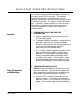
QUICK-START OPERATING INSTRUCTIONS This manual contains detailed operating instructions for all aspects of the D77X instrument. The following condensed instructions are provided to assist the operator in getting the instrument started up and running as quickly as possible. This pertains to basic operation only. If specific instrument features are to be used or if the installer is unfamiliar with this type of instrument, refer to the appropriate section in the manual for complete details. Location 1.
QUICK-START OPERATING INSTRUCTIONS Insertion Depth = (pipe I.D. inches) X 0.125 + 0.67 inches or (pipe I.D. mm) X 0.125 + 17 mm B. Secure the probe insertion distance using the upper and lower brass jam nuts located on the threaded rods. C. Loosen the set screw located in the probe retaining collar with the enclosed allen wrench. D. Rotate the probe body till the arrowhead, located on the top of the probe, is parallel with the pipe and points down stream in the direction of flow. E.
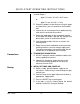
TABLE OF CONTENTS Pages Quick-Start Operating Instructions Part 1 - Introduction Part 2 - Installation Introduction General 3 Applications 3 Model Matrix 5 Product Specifications 7-8 Bench Test Procedure 9-10 Installation Transducer Mounting Locations Probe Retracting Part 3 - Startup and Configuration 11-18 19 Transmitter Installation 20-21 Electrical Connections 22-23 Instrument Startup and Configuration Initial Settings Keypad Operations Rev.
TABLE OF CONTENTS Pages Part 4 - Troubleshooting Trouble Shooting Guide Part 5 - Appendices Appendices 37-38 39+ Spare Parts Listing Face Plate Drawing Pipe Dimension Chart: Cast Iron Intrinsic Safety Connections Pipe Dimension Chart: ST, SS, PVC Velocity to Volumetric Conversion Chart Statement of Warranty Customer Service Rev.
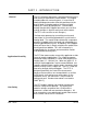
PART 1 - INTRODUCTION General The D77 ultrasonic flow meter is designed to measure the fluid velocity of liquid within closed conduit. The rugged insertion probe has no moving parts, is insensitive to coating buildup and can be accurately positioned at the precise depth in the pipe required to measure liquid velocity in a variety of liquid phases. (Conventional, through the pipe wall, Doppler flow meters are sensitive to large changes in liquid viscosity and solids content.
PART 1 - INTRODUCTION Battery Backup Product Identification A rechargeable nickel-cadmium battery on the back of the display board retains all user-entered configuration values in memory for several years (at 25?C), even if power is lost or turned off. The ten year battery is continually trickle charged whenever line power is applied. A completely discharged battery recharges fully after 48 hours of instrument operation.
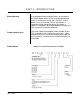
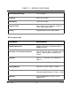
PART 1 - SPECIFICATIONS Description Specification Power Requirements (Std) 110/220 VAC 50/60 Hz ? 5%. (Opt) 100/200 VAC 50/60 Hz ? 5% and 12/24 VDC. Power consumption less than 12 VA. Velocity 0.12 - 30 FPS [ 0.03 – 9.1 MPS] Outputs 4-20 mA, 1000 Ohms max., Isolated. 12 Vdc pulse, 100 ? S duration, 10 Hz max, pulses with totalizer increments Two Relays, 5A @ 250VAC resistive, SPDT Display 2 line x 20 character alphanumeric LCD, back lit. Digit height 0.
PART 1 - SPECIFICATIONS Non-linearity (Accuracy) ? 2% Full Scale Sensitivity 0.05% of Full Scale Repeatability ? 0.2% of Full Scale Response Time 5-50 seconds, user configured, to 90% of value, step change in flow. Security Keypad lockout, access code enable DT7 Insertion Probe Description Specification Liquid Requirements 25 ppm of 30 micron suspended solids or bubbles minimum Transducer to Transmitter Distance (Std) 15 feet [ 4.6 meters ], flexible armored conduit.
PART 2 - PRE-INSTALLATION CHECKOUT Unpacking Functional Test After unpacking, it is recommended to save the shipping carton and packing materials in case the instrument is stored or re-shipped. Inspect the equipment and carton for damage. If there is evidence of shipping damage, notify the carrier immediately. The D77 flow meter can be checked for basic functionality using the following Bench Test procedure. It is recommended that this operation be performed before permanently installing the system.
PART 2 - PRE-INSTALLATION CHECKOUT transducer) with the handle of a screwdriver or similar blunt instrument. 8. Verify that signal strength increases with frequency of the tapping. Typical increases will range from 20-30 counts. 9. Verify that signal strength decreases when tapping ceases. Bench Test is Complete Rev.
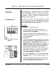
PART 2 - TRANSDUCER INSTALLATION Transducer Mounting Considerations Step A - Mounting Locations The DT7 insertion transducer that is utilized by the D77 contains piezo electric crystals for transmitting and receiving ultrasonic sound energy. The black PVDF plastic tip of the DT7 contains these crystals, which are designed to be inserted to the average fluid velocity point within a pipe. Not all liquid within a pipe is flowing at a uniform fluid velocity.
PART 2 - TRANSDUCER INSTALLATION Table 1 Straight Pipe Recommendations1 1 The D77 system will provide repeatable measurements on piping systems that do not meet these requirements, but the accuracy of these readings may be influenced to various degrees. Rev.
PART 2 - TRANSDUCER INSTALLATION Step B - Hot Tapped Installation The installation instructions cover Hot-Tapped installations (installations where it is required to install or remove the transducer probe without shutting down the process pressure). If the product is being installed without an isolation valve, ignore the steps that pertain to its installation. Figure 3 illustrates an exploded view of an isolation valve assembly and names the various components.
PART 2 - TRANSDUCER INSTALLATION Step C - Component Assembly Procedures are as follows: 1.Verify rated that the pipe’s line pressure is limits of the pressure drilling machine to be used. 2. Grind off paint or other coatings from the pipe in the area where the DT7 Probe Assembly is to be installed. Recommended minimum straight pipe lengths for best accuracy are 10 diameters upstream and 5 downstream. 3.
PART 2 - TRANSDUCER PART 2 -INSTALLATION Step D - Probe Insertion Distances PROBE INSERTION Before beginning the probe insertion procedure, it is necessary to calculate the probe insertion depth of the sensor. For normal pipe runs, the probe tip must be located at 1/8th of the pipe inside diameter. Figure 4 outlines the Necessary measurements and calculations that will be needed to insure that the probe tip is at the proper insertion point.
PART 2 - TRANSDUCER INSTALLATION In order to calculate the proper insertion depth of the probe several pieces of data will have to be collected. The following five constants defines the variables found in the insertion depth calculation. P= The overall length of the probe. This measurement is taken form the top of the probe flange to the very tip of the sensor. Subtract 0.67" from this measurement and record this figure.
PART 2 - TRANSDUCER INSTALLATION Step E - Cable Routing PROBE CABLES Before inserting the probe into the pipe, the sensor cables should be routed to the transmitter location. Verify that the supplied cable length is sufficient to meet the installation requirements. If the supplied length is found to be insufficient, contact the factory to make probe exchange arrangements. CAUTION: Do not proceed with probe insertion should the supplied cable length be insufficient for the installation.
PART 2 - TRANSDUCER INSTALLATION CAUTION: Do Not Force the Probe Tip Against the "Ball", damage to the probe tip may result. 2. Replace the upper Jam Nuts ( 2 on each rod) and the cotter pins. The nuts should be run down to the top side of the retaining collar and the cotter pins replaced. Orient the probe in the direction of flow as indicated on by the FLOW direction arrow located on the top of the probe flange. See Figure 5. Lock the probe in position with the enclosed allen wrench.
PART 2 - TRANSDUCER INSTALLATION Retracting the Probe PROBE RETRACTION PROCEDURE 1. Retract the Probe by loosening the Upper Jam nuts counterclockwise as viewed from the top of the probe using the proper size wrench. If the pipe is under pressure, the nuts must be turned alternately about two turns at a time to prevent, binding as a result of non-equal seal loading. In many cases, the line pressure will cause the probe to retract.
PART PART22- -TRANSMITTER ELECTRICAL CONNECTIONS INSTALLATION Transmitter Installation The D77 enclosure should be located in an area that is convenient for observation of the LCD readout and keypad operations. 1. Place the D77 transmitter in a location that is: ? Where little vibration exist. ? Protected from falling corrosive fluids. ? Within ambient temperature limits - 22 to 122°F [30 to 50°C] ? Out of direct sunlight.
PART PART 22 -- TRANSMITTER SERVICE AND MAINTENANCE INSTALLATION FIGURE 6 To access terminal strips for electronic connectors, loosen the two screws in the enclosure door and open the door. Important ! Rev. 12/97 NOTE: The transducer cable carries low level signals. Do not attempt to add additional cable to the factory supplied transducer cable.
PART PART 22 -- TRANSMITTER SERVICE AND MAINTENANCE INSTALLATION 4-20mA OUTPUT The 4-20mA output is proportional to the flow rate measuring scale and can drive a load of up to 1000 ohms. The output is isolated from earth ground and circuit low. Connect the load to the 4-20 mA connection terminals located on the inside of the D77 enclosure, matching polarity as indicated. Power Connections Line power is connected by supplying power to the appropriate terminals located inside of the D77 enclosure.
PART 2 - TRANSMITTER INSTALLATION If additional cable is required, contact the Dynasonics factory to arrange for an exchange transducer with the appropriate length of cable. Cables to 300 feet [90 meters] are available. NOTE: An additional hole in the transmitter enclosure is required for outputs. Drill the hole in the the enclosure bottom taking care not to drive the drill bit into wiring or the circuit boards with the transmitter.
PART 3 - STARTUP AND CONFIGURATION Before Starting the Instrument Note: The D77/DT7 flow meter system requires a full pipe of liquid before a successful startup can be completed. Do not attempt to make adjustments or change configurations until a full pipe is verified. Instrument Startup Procedure: 1. Verify that all wiring is properly connected and routed. 2. Apply power. The POWER indicator will illuminate. 3. Press the SIGNAL STR key and verify SIGNAL STR counts greater than 100.
PART 3 - KEYPAD CONFIGURATION After a successful flow meter installation and startup (covered in the previous sections of this manual) the D77 can be keypad configured to provide select engineering unit readings of flow and a scaled 4-20mA output. Configuration inputs are made via the keypad and are stored by the microprocessor. The entries are retained by the flow meter’s backup battery in the event of power failure.
PART 3 - KEYPAD CONFIGURATION F1 and F2 Not utilized. RESET Caution: Conducts a system reset. All configuration constants will be lost and the D77 will load default values for all constants. I.D. Allows entry of a pipes internal diameter. Internal diameters must be entered if volumetric flow rates are to be displayed. ? If a UNITS code for U.S. measurements was made the I.D. value will be entered in inches. Valid ranges for this entry are 0.25 to 120.00 inches.
PART 3 - KEYPAD CONFIGURATION ? If a UNITS code for U.S. measurements was made the FULL SCALE value will be entered in FPS (feet per second). Valid ranges for this entry are 0.00 to 30.00 FPS. Two useful equations that relate liquid velocity to volume: GPM = 2.45 X I.D.2 X FPS FPS = ( GPM X 0.408) / I.D.2 I.D. in inches ? If a UNITS code for metric measurement was made the I.D. value will be entered in MPS (meters per second). Valid ranges for this entry are 0 to 10.00 MPS.
PART 3 - KEYPAD CONFIGURATION Table 2 UNITS Code Flow Rate Rev. 12/97 Totalizer 0 FPS (feet per sec) 1 GPM (gallons per min) GALLONS 2 GPH (gallons per hr) GALLONS 3 MGD (millions of gal pre day) GALLONS 4 CFM (ft.
PART 3 - KEYPAD CONFIGURATION HIGH ALARM (Labeled RELAY-1 on the Main PCB) Controls the set-point of the SPDT relay labeled RELAY-1 on the Main PCB. Enter a liquid velocity at which a relaycontact action is desired. Relay contacts are utilized for signaling flow rate conditions that are higher of lower than a desired set point. If a relay setting is made very close to a nominal liquid velocity, relay “cha tter” ( rapid opening and closing of the relay ) may result. ? If a UNITS code for U.S.
PART 3 - KEYPAD CONFIGURATION useful for accommodating a very large accumulated flow. The exponent is a “ X 10n” multiplier, were “n” can be from 0 (100, X 1 multiplier) to 4 (104, X 10,000 multiplier). The External Counter output, available at the two terminals labeled CTR on the Main PCB, is influenced by the TOTAL MULT value.
PART 3 - KEYPAD CONFIGURATION (continued) Third press Restarts the internal totalizer/external CTR (The internal totalizer starts from zero.) If inhibiting (pausing) the totalizer is necessary, there are two methods suggested: 1. Connect and external totalizer to the CTR terminals. See the section of this manual related to CTR electrical connections for connection parameters. 2. To inhibit the internal totalizer without resetting the accumulation, press the TEST key to pause the accumulation.
PART 3 - KEYPAD CONFIGURATION ? Transducer mounted in non-recommended locations. By applying a CAL value other than 100%, the factorycalibrated readings will be altered by the percentage entered. This CAL value will be reflected in the display, 420mA and CTR outputs and relay settings. For example, if a reading of 175 GPM is displayed and the known flow rate is 160 GPM, a CAL value of 160 GPM x 100 = 91.
PART 3 - KEYPAD CONFIGURATION {2nd FUNCT} SIGNAL STR Displays the raw Doppler signal strength value. This value will increase as the velocity of the liquid increases. Typically, a liquid flowing at a velocity greater than 0.2 FPS [0.06 MPS], with adequate suspended solids (25 ppm or 30 micron or larger solids) or aeration, will produce SIGNAL STR readings over 150 counts. NOTE: If the liquid is not flowing a low SIGNAL STR reading is non-conclusive.
PART 3 - KEYPAD CONFIGURATION at zero flow equals 4mA and 20 FPS (6.08 MPS) equals 20mA. The 4mA key allows fine adjustments to be made to the “zero” of the 4-20mA output or allows offset to be placed on the 4-20mA output. To adjust the 4mA output, an ammeter or reliable reference connection to the 420mA output must be present. Procedure: 1.
PART 3 - KEYPAD CONFIGURATION at zero flow equals 4mA and 20 FPS (6.08 MPS) equals 20mA. The 20mA key allows fine adjustments to be made to the “span” of the 4-20mA output. To adjust the 20mA output, an ammeter or reliable reference connection to the 4-20mA output must be present. Procedure: 1.
PART 3 - KEYPAD CONFIGURATION instrument will operate. Choices are 10, 20 and 30 FPS. It is not recommended to deviate alter this value from factory settings, as certain spans have been set that correlate to the set maximum velocity. Consult the Dynasonics factory for adjustment procedures. {2nd FUNCT} DAC 3 This key is not used. {2nd FUNCT} BACK LIGHT Toggles the electro-luminescent LCD back lighting ON and OFF. This type of back lighting has an illumination half-life of approximately one year.
PART 4 - TROUBLE SHOOTING CONDITION POSSIBLE CAUSE Unit does not turn “ON” when power is applied ? Verify that AC power source is live. ? Test the fuse ? Ensure that the transducer is properly mounted to the pipe. ? Verify that transducer connections are correct ? Ensure that the pipe is full of moving liquid. ? If SIGNAL STR is less than 100 counts and flow rate is greater than 1 FPS [0.3 MPS], adjust GAIN control (R13 on the Main PCB) till SIGNAL STR reaches at least 130 counts.
PART 4 - TROUBLE SHOOTING Stability of flow readings are unsatisfactory ? Increase the DAMP constant from keypad. ? Move transducers to a location further from piping tees, elbows, valves, filters, etc. ? Transducer mounted incorrectly or not true to the pipe. ? Another local ultrasonic instrument is operating at about the same frequency [ consult the Dynasonics factory]. ? Presence of large amounts of suspended solids or aeration. Use CAL constant to compensate.
PART 5 - APPENDICES Appendices Spare Parts List Face Plate Drawing Intrinsic Safety Connections Pipe Dimension Chart: Cast Iron Pipe Dimension Chart: Steel, SS, PVC Velocity to Volumetric Conversion Chart Statement of Warranty Customer Service Rev.
SPARE PARTS - D77/DT77 Description Dynasonics Part Number Series D77 Main PCB D020-1042-051 Series D77 Micro PCB D020-1038-005 Series D77 Enclosure w/keypad D040-0121-001 D77 Installation and Operations Manual D77 O&M Two conductor, 20 AWG wire Stainless Steel I.D. Tag Probe Seal Kit DSS TAG D003-0135-000 Bronze Ball Valve Kit, 1 -1/2” NPT Rev.
Ductile Iron Pipe Standard Classes Pipe Outside Size Diameter (inches) (inches) Class 50 Class 51 Class 52 Class 53 Class 54 Class 55 Class 56 ID Wall ID Wall ID Wall ID Wall ID Wall ID Wall ID Wall 0.25 0.26 0.28 0.30 0.32 0.34 3.40 4.22 6.28 8.39 10.40 12.46 0.28 0.29 0.31 0.33 0.35 0.37 3.34 4.16 6.22 8.33 10.34 12.40 0.31 0.32 0.34 0.36 0.38 0.40 3.28 4.10 6.16 8.27 10.28 12.34 0.34 0.35 0.37 0.39 0.41 0.43 3.22 4.04 6.10 8.21 10.22 12.28 0.37 0.38 0.40 0.42 0.44 0.46 3.
Cast Iron Pipe Standard Classes CLASS A Size O.D. (Inches) Inch CLASS B CLASS C CLASS D CLASS E I.D. O.D. Wall Inch Inch I.D. O.D. Wall Inch Inch I.D. O.D. Wall Inch Inch I.D. O.D. Wall Inch Inch CLASS F CLASS G CLASS H I.D. O.D. Wall Inch Inch I.D. O.D. Wall Inch Inch I.D. O.D. Wall Inch Inch I.D. Inch Wall 3 3.80 3.02 0.39 3.96 3.12 0.42 3.96 3.06 0.45 3.96 3.00 0.48 4 4.80 3.96 0.42 5.00 4.10 0.45 5.00 4.04 0.48 5.00 3.96 0.52 6 6.90 6.02 0.44 7.10 6.14 0.48 7.10 6.08 0.
Steel, Stainless Steel, P.V.C. Standard Schedules Nominal OUTSIDE Pipe Size DIAMETER Inches SCH. 5 SCH. 10 (LTWALL) SCH. 20 SCH. 30 ID ID ID Wall ID Wall Wall Wall STD. ID Wall SCH. 40 SCH. 60 ID Wall ID Wall X STG. SCH. 80 SCH. 100 SCH. 120 SCH. 140 SCH. 180 ID ID ID ID Wall 0.815 1.160 1.338 1.687 2.125 2.624 0.250 0.250 0.281 0.344 0.375 0.438 ID Wall ID Wall 1 1.25 1.5 2 2.5 3 1.315 1.660 1.900 2.375 2.875 3.500 1.185 1.530 1.770 2.245 2.709 3.334 0.065 0.
FPS TO GPM CROSS - REFERENCE (Schedule 40) Nominal I.D. Pipe INCH (Inches) 1 1.5 2 2.5 3 3.5 4 4.5 5 5.5 6 6.5 7 7.5 8 8.5 9 1 1.05 2.6989 4.0484 5.3978 6.7473 8.097 9.4462 10.796 12.145 13.490 14.844 16.190 17.540 18.890 20.240 21.590 22.941 24.290 1.25 1.38 4.6620 6.9929 9.3239 11.655 13.99 16.317 18.648 20.979 23.310 25.641 27.970 30.300 32.630 34.960 37.300 39.627 41.958 1.5 1.61 6.3454 9.5182 12.691 15.864 19.04 22.209 25.382 28.555 31.730 34.900 38.070 41.250 44.420 47.
FPS TO GPM CROSS - REFERENCE (Schedule 40) Nominal I.D. Pipe INCH (Inches) 1 1.5 2 2.5 3 3.5 4 4.5 5 5.5 6 6.5 7 7.5 8 8.5 9 18 16.88 697.52 1046.3 1395.0 1743.8 2093.0 2441.3 2790.1 3138.8 3488.0 3836.3 4185.0 4534.0 4883.0 5231.0 5580.0 5928.9 6277.7 20 18.81 866.14 1299.0 1732.0 2165.3 2598.4 3031.5 3464.6 3897.6 4330.7 4763.8 5196.8 5629.9 6063.0 6496.0 6929.1 7362.2 7795.3 24 22.63 1253.7 1880.0 2507.0 3134.1 3761.0 4387.8 5014.6 5641.5 6268.3 6895.1 7522.0 8148.8 8775.6 9402.
Limited Warranty and Disclaimer Dynasonics, div. of Racine Federated Inc. warrants to the end purchaser, for a period of one year from the date of shipment from our factory, that all new transmitters and transducers manufactured by it are free from defects in materials and workmanship. This warranty does not cover products that have been damaged due to normal use, misapplication, abuse, lack of maintenance, or improper installation.
GENERAL TERMS AND CONDITIONS OF SALES 1. PAYMENT – Terms of payment are effective from the actual date of invoice. If, in the Seller’s opinion, the financial condition of the Buyer at any time – or any other circumstances – do not justify the incurrence of production costs of shipment on the terms of payment specified, the Seller may require partial or full payment in advance. Payment terms are net 30 days unless otherwise stated on invoice. 2. F.O.B.
DIVISION OF RACINE FEDERATED INC. 2200 SOUTH STREET, RACINE, WI 53404 RETURN OF EQUIPMENT/SALES INFORMATION CONTACTS AND PROCEDURES Customer Service/Application Engineer: If you have a question regarding order status, placing an order, reviewing applications for future purchases, or wish to purchase a new flowmeter, please contact our new National Sales and Marketing Headquarters: DYNASONICS Division of Racine Federated, Inc.
2200 SOUTH STREET RACINE, WI 53404 TOLL-FREE IN North America: TEL: (800) 535-3569 TEL: (262) 639-6770 FAX: (262) 639-2267 URL: www.dynasonics.