
User guide

Rev. 12/97 -2- D77X
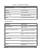
Insertion Depth =
(pipe I.D. inches) X 0.125 + 0.67 inches
or
(pipe I.D. mm) X 0.125 + 17 mm
B. Secure the probe insertion distance using the upper
and lower brass jam nuts located on the threaded
rods.
C. Loosen the set screw located in the probe retaining
collar with the enclosed allen wrench.
D. Rotate the probe body till the arrowhead, located
on the top of the probe, is parallel with the pipe and
points down stream in the direction of flow.
E. Lock the probe rotation with the set screw in the
retaining collar.
F. Route the transducer cable back to the transmitter,
avoiding locations near high voltage supply wires.
Transducer connections are made through the left
conduit hole in the bottom of the transmitter.
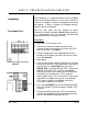
3. TRANSDUCER CONNECTION
A. DO NOT attempt to connect additional cable to the
factory supplied transducers.
B. Connect the transducer spade terminals to the
XDCR terminal block located on the lower left
corner of the main PCB.
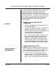
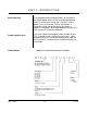
4. INITIAL SETTINGS AND POWER UP
A. Route a stable, grounded power supply to the
transmitter. Power wiring is made through the right
conduit hole.
B. Connect Power to the upper right terminal block as
appropriate. Apply power.
C. Press the RESET key on the keypad.
D. If the pipe is full of a flowing liquid, the default
readings will be FPS (Feet per Second).
Startup
Connections
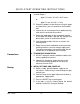
QUICK-START OPERATING INSTRUCTIONS