Series 902/903 Portable Doppler Ultrasonic Flow Meter Operations & Maintenance Manual REV 10/08
BEFORE OPERATING THE D902/3 Important Notice! The D902/3 flow meter is equipped with a Lead Acid Gel Cell battery. This battery will require charging before initial operation. Apply AC power, utilizing the enclosed line power cord, to the D902/3 for a period of 16-24 hours prior to using the product for the first time. The line cord connects to the socket connection located on the side of the enclosure. Do not allow the battery to completely discharge.
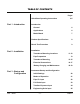
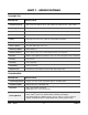
TABLE OF CONTENTS Pages Quick-Start Operating Instructions Part 1 - Introduction Part 2 - Installation Introduction General 6 Applications 6 Model Matrix 7 Product Specifications 8 Bench Test Procedure 9 Installation Transducer Mounting Locations Pipe Preparation Part 3 - Startup and Configuration Rev.
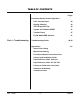
TABLE OF CONTENTS Pages Instrument Startup and Configuration Part 4 - Troubleshooting CAL.
QUICK-START OPERATING INSTRUCTIONS This manual contains detailed operating instructions for all aspects of the D902/3 instrument. The following condensed instructions are provided to assist the operator in getting the instrument started up and running as quickly as possible. This pertains to basic operation only. If specific instrument features are to be used or if the installer is unfamiliar with this type of instrument, refer to the appropriate section in the manual for complete details. 1.
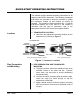
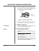
QUICK-START OPERATING INSTRUCTIONS D. Place each transducer under the mounting strap, 180° apart on the pipe. Ensure that the transducer cables are facing the same direction. See Figure 2. FLOW DIRECTION Figure 2 Transducer Cable Direction E. Route the transducer cable back to the transmitter, avoiding locations near high voltage supply wires. Connections Startup 3. TRANSDUCER CONNECTION A. Connect the transducer plug to the appropriate mating socket on the side the D902/3 enclosure. 4.
PART 1 - INTRODUCTION General The D902/3 ultrasonic flow meter is designed to measure the fluid velocity of liquid within closed conduit. The transducers are a non-contacting, clamp-on type, which will provide benefits of non-fouling operation and ease of installation. The flow meter operates by transmitting an ultrasonic sound from its transmitting transducer through the pipe wall into the flowing liquid.
PART 1 - INTRODUCTION The D902/3 employs modular construction and provides electrical safety for the operator. The display face contains voltages no greater than 9 Vdc and the metal work is electrically connected to earth ground. All user connections are made through sealed, bulk-head plugs located on the side of the D902/3 enclosure.
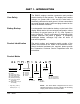
PART 1 - SPECIFICATIONS TRANSMITTER DESCRIPTION SPECIFICATION Power Requirements Internal Lead Acid Gel Cell battery provides 8 hours of continuous operation. AC charging: (Std) 115/230 VAC 50/60 Hz ±10%. (Opt) 100/200 VAC 50/60 Hz ±10%. (Opt) 12 VDC. Flow Range 0.5 to 20 FPS (0.15 to 6 MPS) Outputs 4-20 mA, 600 Ohms max. isolated Indicators Power, Signal Strength, Flow Analyzer, Read Fault, Overrange, Charging and Low Battery Display 2 line × 20 character alphanumeric LCD (backlit).
PART 2 - PRE-INSTALLATION CHECKOUT Unpacking Functional Test After unpacking, it is recommended to save the shipping carton and packing materials in case the instrument is stored or re-shipped. Inspect the equipment and carton for damage. If there is evidence of shipping damage, notify the carrier immediately. The D902/3 flow meter can be checked for basic functionality using the following Bench Test procedure. It is recommended that this operation be performed before each day of operation. Procedure: 1.
PART 2 - TRANSDUCER INSTALLATION Transducer Mounting Considerations The transducers that are utilized by the D902/3 contain piezoelectric crystals for transmitting and receiving ultrasonic sound energy through the pipe wall. The transducers can be mounted in three different configurations. The selection of the proper configuration is dependent on the characteristics of the liquid to be measured.
PART 2 - TRANSDUCER INSTALLATION Table 11 1 The D902/3 system will provide repeatable measurements on piping systems that do not meet these requirements, but the accuracy of these readings may be influenced to various degrees. Rev.
PART 2 - TRANSDUCER INSTALLATION CASE 2: Liquid that contains greater than 10,000 PPM (1%) of 30 micron or greater suspended solids or aeration. The mounting location and straight pipe requirements for CASE 2 liquid characteristics are the same as those described in CASE 1. The difference will be in the location of the transducers on the pipe.
PART 2 - TRANSDUCER INSTALLATION Figure 6 Step B Pipe Surface Preparation Before the transducer heads are bonded to the pipe surface, an area slightly larger than the flat surface of the transducer must be cleaned to bare metal on the pipe. (Plastic pipes do not require preparation beyond removal of paint.) Remove all scale, rust and paint. Thoroughly dry and degrease the mounting surfaces.
PART 2 - TRANSDUCER INSTALLATION To assure an acoustically conductive path between the transducer face and the prepared piping surface, a coupling compound is employed. Enclosed with the D902/3 system is a tube of Dow Corning 111, silicone grease. This couplant is satisfactory for temporarily mounting the transducers to the pipe. If the installation is long-term (more than a few days), Dynasonics recommends utilizing a silicone-based RTV such as Dow Corning RTV-732.
PART 2 - TRANSDUCER INSTALLATION 6. Route the transducer cable back to the transmitter mounting area avoiding high voltage cable trays and conduits. Do not attempt to add additional cable to the factory supplied transducer cable. The D902/3 processes very small signals, so the cable shield must be continuous. 7. If the transducers are to be permanently mounted using Dow 732, the RTV must be completely cured before proceeding to Instrument Startup.
PART 2 - ELECTRICAL CONNECTIONS Transmitter Location The D902/3 enclosure should be located in an area that is convenient for observation of the LCD readout and keypad operations. To prolong the life of the keypad and controls, the enclosure cover should be left closed when the unit is unattended. Place the D902/3 transmitter in a location that is: ♦ Where little vibration exists. ♦ Protected from falling corrosive fluids.
PART 2 - ELECTRICAL CONNECTIONS 4-20 mA Output Battery Charging and AC Power Operation 4-20 mA Output The 4-20 mA output is proportional to the flow rate measuring scale and can drive a load of up to 600 Ohms. The output is isolated from earth ground and circuit low. Connect the load to the 4-20 mA connection socket located on the side of the D902/3 enclosure, matching polarity as indicated. See Figure 9. A mating plug for the connection socket has been included.
PART 2 - SERVICE AND MAINTENANCE Battery Care and Maintenance The D902/3 flow meter is equipped with a Lead Acid Gel Cell battery. This battery will require charging before initial operation. Apply AC power, utilizing the enclosed line power cord, to the D902/3 for a period of 16-24 hours prior to using the product for the first time. The line cord connects to the socket connection located on the side of the enclosure.
PART 2 - SERVICE AND MAINTENANCE Desiccant Cartridge The D902/3 is equipped with a DESICCANT CARTRIDGE, which is located in the face plate of the meter. The purpose of the cartridge is to absorb the humidity that was present inside of the enclosure when the product was manufactured and to absorb moisture that may seep into the enclosure during field operation.
PART 3 - STARTUP AND CONFIGURATION Before Starting the Instrument NOTE: The D902/3 flow meter system requires a full pipe of flowing liquid before a successful startup can be completed. Do not attempt to make adjustments or change configurations until both a full pipe and liquid flow are verified. NOTE: If Dow 732 RTV was utilized to couple the transducers to the pipe, the adhesive must fully cure before power is applied to the instrument. Dow 732 requires 24 hours to cure satisfactorily.
PART 3 - STARTUP AND CONFIGURATION Keypad Configurations After a successful flow meter installation and startup (covered in the previous sections of this manual) the D902/3 can be keypad configured to provide select engineering unit readings of flow and a scaled 4-20 mA output. Configuration inputs are made via the keypad and are stored by the microprocessor. The entries are retained by the flow meter’s backup battery in the event of power failure.
PART 3 - STARTUP AND CONFIGURATION Pipe I.D. Input The ID key allows the entry of a pipe’s Internal Diameter. The D902/3 utilizes the I.D. constant to process volumetric flow rates such as GPM (Gallons per Minute) or LPM (Liters per Minute). The entry is made as either inches or mm, dependent on whether the unit is configured as U.S. units or Metric units. Press the I.D. key from the ENTRY MODE. The display will show INSIDE DIAMETER This is the present I.D. constant. Enter a new I.D.
PART 3 - STARTUP AND CONFIGURATION Full Scale Input The FULL SCALE key allows the entry of the highest anticipated fluid velocity. The entry is made as either FPS (Feet per Second) or MPS (Meters per Second) dependent on whether the unit is configured as U.S. units or Metric units. The FULL SCALE input is used by the D902/3 microprocessor to scale the 4-20 mA output and adjust the resolution of the flow rate display. Acceptable input range for the FULL SCALE constant is shown in Table 4.
PART 3 - STARTUP AND CONFIGURATION Totalizer Exponent Input The VOL. PULSE key allows the entry of a totalizer exponent. This feature is useful for accommodating a very large accumulated flow. The exponent is a “×10” multiplier, which can be from 0 (no multiplier) to 2 (×100). For example, to totalize in GAL × 100, a VOL. PULSE value of 2 would be used (10² or 100). Acceptable input range for the VOL. PULSE constant is shown in Table 5. Table 5 I.D. U.S.
PART 3 - STARTUP AND CONFIGURATION Engineering Units Input The UNITS key allows the selection of measuring units. Table 7 shows applicable codes for the engineering units available. Table 7 UNITS CODE U.S. METRIC 1 FPS MPS 2 GPM LPM 3 MGD LPS Attempting to enter values other than 1, 2 or 3 will result in an UNDER! or OVER! to be displayed. Non-whole number values will result in a RANGE! display. A legitimate value must be entered.
PART 3 - STARTUP AND CONFIGURATION The D902/3 will not allow decimal values to be entered as a CAL constant, so round to the nearest whole number. In this case 91%. Acceptable input ranges for the CAL constant are shown in Table 8. Values outside of this range will result in an OVER! or UNDER! display. Non-whole number entries will result in a RANGE! display. Enter an appropriate value. Table 8 Display Damping I.D. U.S.
PART 3 - STARTUP AND CONFIGURATION System and Totalizer RESET The RESET key is used for generating a system reset or to reset the accumulated flow. Press the RESET button from the ENTER Mode. A choice is then made to: RESET Reset the system VOL. MULT Press VOL. PULSE to reset the totalizer to zero If the RESET key is pressed again, all configuration constants will return to default values. If the VOL. PULSE key is pressed, the accumulated flow will be erased and the display will return to zero.
PART 4 - TROUBLESHOOTING CONDITION POSSIBLE CAUSE Unit does not turn “ON” when power is applied These procedures require the face plate to be removed from the enclosure. OVERRANGE light is ON FAULT light is ON; low SIGNAL STRENGTH indication • Verify that the battery is charged. into an AC power source. • Test the fuse. • Ensure the terminal block located in the upper left corner of the main PCB is secure. • Verify that ribbon cables between PCBs are connected.
PART 4 - TROUBLESHOOTING FAULT light is ON; low SIGNAL STRENGTH indication (continued) Stability of flow readings are unsatisfactory This procedure requires the face plate to be removed from the enclosure. Erroneous Reading The D902/3 display indicates flow, when true fluid velocity is zero Rev. 10/08 • If GND connection and pipe are at different potentials, ground D902/3 to pipe potential.
NOTES Rev.
PART 5 - APPENDICES Appendices Spare Parts List Mechanical Drawing Fluid Sound Speed Conversion Chart Clean Liquid Installation Guide Pipe Dimension Chart: Cast Iron Pipe Dimension Chart: Steel, SS, PVC Velocity to Volumetric Conversion Chart Statement of Warranty Customer Service Rev.
SPARE PARTS - D902/3 Rev. 10/08 PART NUMBER DESCRIPTION D070-1004-001 Series D902 Std. Temp./Std. Pipe Transducer D040-0402-001 Series D902 High Temp./Std. Pipe Transducer D070-1004-003 Series D902 Std. Temp.
MECHANICAL DRAWING - D902/3 Rev.
Fluid Properties Original Date: Revision: Revision Date: File: Fluid Acetate, Butyl Acetate, Ethyl Acetate, Methyl Acetate, Propyl Acetone Alcohol Alcohol, Butyl Alcohol, Ethyl Alcohol, Methyl Alcohol, Propyl Alcohol, Propyl Ammonia Anlline Benzene Benzol, Ethyl Bromine n-Butane Butyrate, Ethyl Carbon dioxide Carbon tetrachloride Chloro-benezene Chloroform Diethyl ether Diethyl Ketone Diethylene glycol Ethanol Ethyl alcohol Ether Ethyl ether Ethylene glycol Freon R12 Gasoline Glycerin Glycol Isobutanol Is
Oil, Castor Oil, Diesel Oil (Lubricating X200) Oil (Olive) Oil (Peanut) Paraffin Oil Pentane Petroleum 1-Propanol Refrigerant 11 Refrigerant 12 Refrigerant 14 Refrigerant 21 Refrigerant 22 Refrigerant 113 Refrigerant 114 Refrigerant 115 Refrigerant C318 Silicone (30 cp) Toluene Transformer Oil Trichlorethylene 1,1,1-Trichloro-ethane Turpentine Water, distilled Water, heavy Water, sea Wood Alcohol m-Xylene o-Xylene p-Xylene 0.97 0.80 0.91 0.94 0.626 0.876 0.78 1.49 1.52 1.75 1.43 1.49 1.56 1.46 1.62 0.99 0.
Cast Iron Pipe Standard Classes CLASS A Size O.D. (Inches) Inch CLASS B CLASS C CLASS D CLASS E I.D. O.D. Wall Inch Inch I.D. O.D. Wall Inch Inch I.D. O.D. Wall Inch Inch I.D. O.D. Wall Inch Inch CLASS F CLASS G CLASS H I.D. O.D. Wall Inch Inch I.D. O.D. Wall Inch Inch O.D. I.D. Wall Inch Inch I.D. Inch Wall 3 3.80 3.02 0.39 3.96 3.12 0.42 3.96 3.06 0.45 3.96 3.00 0.48 4 4.80 3.96 0.42 5.00 4.10 0.45 5.00 4.04 0.48 5.00 3.96 0.52 6 6.90 6.02 0.44 7.10 6.14 0.48 7.10 6.08 0.
Steel, Stainless Steel, P.V.C. Standard Schedules Nominal OUTSIDE Pipe Size DIAMETER Inches SCH. 5 SCH. 10 (LTWALL) SCH. 20 SCH. 30 ID ID ID Wall ID Wall Wall Wall STD. ID Wall SCH. 40 SCH. 60 ID Wall ID Wall X STG. SCH. 80 SCH. 100 SCH. 120 SCH. 140 SCH. 180 ID ID ID ID Wall 0.815 1.160 1.338 1.687 2.125 2.624 0.250 0.250 0.281 0.344 0.375 0.438 ID Wall ID Wall 1 1.25 1.5 2 2.5 3 1.315 1.660 1.900 2.375 2.875 3.500 1.185 1.530 1.770 2.245 2.709 3.334 0.065 0.
Ductile Iron Pipe Standard Classes Outside Pipe Diameter Size (inches) (inches) Class 50 Class 51 Class 52 Class 53 Class 54 Class 55 Class 56 ID Wall ID Wall ID Wall ID Wall ID Wall ID Wall ID Wall 0.25 0.26 0.28 0.30 0.32 0.34 3.40 4.22 6.28 8.39 10.40 12.46 0.28 0.29 0.31 0.33 0.35 0.37 3.34 4.16 6.22 8.33 10.34 12.40 0.31 0.32 0.34 0.36 0.38 0.40 3.28 4.10 6.16 8.27 10.28 12.34 0.34 0.35 0.37 0.39 0.41 0.43 3.22 4.04 6.10 8.21 10.22 12.28 0.37 0.38 0.40 0.42 0.44 0.46 3.
FPS TO GPM CROSS - REFERENCE (Schedule 40) Nominal I.D. Pipe INCH (Inches) 1 1.5 2 2.5 3 3.5 4 4.5 5 5.5 6 6.5 7 7.5 8 8.5 9 1 1.05 2.6989 4.0484 5.3978 6.7473 8.097 9.4462 10.796 12.145 13.490 14.844 16.190 17.540 18.890 20.240 21.590 22.941 24.290 1.25 1.38 4.6620 6.9929 9.3239 11.655 13.99 16.317 18.648 20.979 23.310 25.641 27.970 30.300 32.630 34.960 37.300 39.627 41.958 1.5 1.61 6.3454 9.5182 12.691 15.864 19.04 22.209 25.382 28.555 31.730 34.900 38.070 41.250 44.420 47.
FPS TO GPM CROSS - REFERENCE (Schedule 40) Nominal I.D. Pipe INCH (Inches) 1 1.5 2 2.5 3 3.5 4 4.5 5 5.5 6 6.5 7 7.5 8 8.5 9 18 16.88 697.52 1046.3 1395.0 1743.8 2093.0 2441.3 2790.1 3138.8 3488.0 3836.3 4185.0 4534.0 4883.0 5231.0 5580.0 5928.9 6277.7 20 18.81 866.14 1299.0 1732.0 2165.3 2598.4 3031.5 3464.6 3897.6 4330.7 4763.8 5196.8 5629.9 6063.0 6496.0 6929.1 7362.2 7795.3 24 22.63 1253.7 1880.0 2507.0 3134.1 3761.0 4387.8 5014.6 5641.5 6268.3 6895.1 7522.0 8148.8 8775.6 9402.
Limited Warranty and Disclaimer Dynasonics, division of Racine Federated Inc. warrants to the end purchaser, for a period of one year from the date of shipment from the factory, that all new transmitters and transducers manufactured by it are free from defects in materials and workmanship. This warranty does not cover products that have been damaged due to misapplication, abuse, lack of maintenance, or improper installation.
GENERAL TERMS AND CONDITIONS OF SALES 1. PAYMENT – Terms of payment are effective from the actual date of invoice. If, in the Seller’s opinion, the financial condition of the Buyer at any time – or any other circumstances – do not justify the incurrence of production costs of shipment on the terms of payment specified, the Seller may require partial or full payment in advance. Payment terms are net 30 days unless otherwise stated on invoice. 2. F.O.B.
RETURN OF EQUIPMENT/SALES INFORMATION CONTACTS AND PROCEDURES Customer Service/Application Engineer: If you have a question regarding order status, placing an order, reviewing applications for future purchases, or wish to purchase a new flow meter, please contact our new National Sales and Marketing Headquarters: DYNASONICS Division of Racine Federated Inc.
8635 WASHINGTON AVENUE RACINE, WI 53406 TOLL-FREE IN NORTH AMERICA TEL: (800) 535-3569 FAX: (800) 732-8354 TEL: (262) 639-6770 FAX: (262) 639-2267 URL: www.dynasonics.com DYNASONICS is a registered trademark of Racine Federated Inc. Ultem is a registered trademark of General Electric Co. Vespel is a registered trademark of E.I. DuPont de Nemours and Company. National Electric Code is a registered trademark of NFPA. UL is a registered trademark of Underwriters Laboratories. © 2008 Racine Federated Inc.