Series D7700 Insertion Doppler Ultrasonic Flow Meter Operations & Maintenance Manual REV 2/00
QUICK-START OPERATING INSTRUCTIONS This manual contains detailed operating instructions for all aspects of the D77X instrument. The following condensed instructions are provided to assist the operator in getting the instrument started up and running as quickly as possible. This pertains to basic operation only. If specific instrument features are to be used or if the installer is unfamiliar with this type of instrument, refer to the appropriate section in the manual for complete details. Location 1.
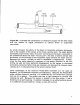
QUICK-START OPERATING INSTRUCTIONS Insertion Depth = (pipe I.D. inches) X 0.125 + 0.67 inches or (pipe I.D. mm) X 0.125 + 17 mm B. Secure the probe insertion distance using the upper and lower brass jam nuts located on the threaded rods. C. Loosen the set screw located in the probe retaining collar with the enclosed allen wrench. D. Rotate the probe body till the arrowhead, located on the top of the probe, is parallel with the pipe and points down stream in the direction of flow. E.
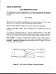
PART 3 - TRANSMITTER INSTALLATION Installation of Transmitter Box The enclosure should be mounted in an area that is convenient for servicing, calibration or for observation of the LCD readout. 1. Locate the transmitter within the length of transducer cable that was supplied with the D7700 system. If this is not possible, do not attempt to add additional cable to the transducer. Contact the Dynasonics factory to coordinate an exchange for the proper cable length.
PART 3 - TRANSMITTER INSTALLATION Figure 3.1 5. If additional holes are required, (analog outputs, etc.) drill the appropriate size hole in the enclosure’s bottom. Use extreme care not to run the drill bit into the wiring or circuits cards. Electrical Connections 1. To access terminal strips for electronic connections, loosen the two screws in the enclosure door and open the door. 2. Guide the transducer terminations through the transmitter conduit hole located on the right side of the enclosure.
PART 3 - TRANSMITTER INSTALLATION transmitter. See the electrical connections detail in Figure 3.2 and 3.3. NOTE: The transducer cable carries low level signals. Do not attempt to add additional cable to the factory supplied transducer cable. If additional cable is required, contact the Dynasonics factory to arrange for an exchange transducer with the appropriate length of cable. Cables to 300 feet [ 90 meters ] are available. Rev. 2/00 -3.
Rev. 2/00 -3.4- 77X 1/16A 3AG Delay Action 115/230 Vac LOW Velocity Filter For measuring fluid velocities up to 20 FPS [6 MPS] set the two switches at SW2 to OPEN. If continuous flow rate will not exceed 2 FPS [0.6 MPS] turn the two switches ON. R10 [GAIN] Control After all electrical and transducer connections have been made, the GAIN control is set to match liquid and pipe parameters. To properly set the R10 [GAIN], the pipe must be full of a flowing liquid.
Rev. 2/00 -3.5- 77X Does not matter LOW Velocity Filter For measuring fluid velocities up to 20 FPS [6 MPS] set the two switches at SW2 to OPEN. If continuous flow rate will not exceed 2 FPS [0.6 MPS] turn the two switches ON. R10 [GAIN] Control After all electrical and transducer connections have been made, the GAIN control is set to match liquid and pipe parameters. To properly set the R10 [GAIN], the pipe must be full of a flowing liquid. Start with the control fully CCW [counter clockwise].
PART 4 - CONFIGURATION AND OPERATION Power Up and GAIN Adjustment After power has been applied to the flowmeter and if the pipe is full of a flowing liquid, the LED located on the bottom of the main circuit card [D21] should begin flashing. If the LED does not flash, gradually turn the GAIN control [R10] clockwise until the LED just begins to flash steadily. (Do not over adjust this setting as ambient noise can influence readings.) If possible, turn off the flow to the pipe.
PART 4 - CONFIGURATION AND OPERATION FIELD CALIBRATION PROCEDURES After the Equipment is properly installed and operating, there may be a need to field calibrate the flowmeter. This could be caused by a number of reasons: 1. Using a size pipe other than the one specified when factory configured. 2. When used to measure a liquid with a sound speed that is different than the one specified when factory configured. 3. When proper lengths of straight pipe are not available. 4.
PART 4 - CONFIGURATION AND OPERATION B. Totalizer Calibration — Series D7701 1. If an oscilloscope or signal counter is available, a signal from test point TP10 will show the totalizer count rate at a particular flow. Refer to the drawing in the Appendix titled 091-1048-102 Series 300 Waveforms. The pulse rate at TP10 can be x 10, x 100, x 1000 or x10,000 of totalizer count rate, at the CTR output on terminal strip.
PART 4 - CONFIGURATION AND OPERATION C.W. Time the new rate and adjust as required. For example, if the flow indicator reads 1,000 GPM and a totalizer count rate of 1 count every 60 seconds should be displayed. If the actual count rate is one count every 50 seconds, then turn the adjustment R90 slightly (with SW 1 Position x 1,000) C.C.W. to decrease the count rate until there is one count on the totalizer every 60 seconds when the flow rate indicator is reading 1,000 GPM.
PART 4 - CONFIGURATION AND OPERATION the Fluid Sound Speed Compensation chart located in the Appendix of this manual. Once a new calibration frequency has been determined, the frequency is input as a 1 Vpp sinewave into TP3 on the main circuit card. This input will simulate full scale flow in the circuit. With the function generator inputting the calibration frequency the SPAN, 1mA, 20mA and CTR inputs can be configured. A 10% and 50% of SPAN frequency can be input and flow meter linearity can be verified.
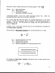
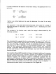
PART 4 - CONFIGURATION AND OPERATION HOW TO CALIBRATE FOR A DIFFERENT SCALE & PIPE This procedure is an outline of how to re-scale the series D7700 flow meter. 1. The first step is to determine the full scale velocity setting. To determine this you would need the full scale setting (i.e. GPM, MGD etc) and the pipe inside diameter (refer to the charts in the Appendix). Example calculation: Full scale 500 GPM. Pipe size: 4.026 inches I.D. Feet per Second = 500 GPM (4.026)2 x 2.45 = 12.755 FPS 2.
PART 4 - CONFIGURATION AND OPERATION the new count rate is 1.2 seconds per count at 10 gallons per count. A digital counter is placed on the output of the circuit card to measure the period between pulses so that at a full scale of 500 GPM the CTR adjustment is set to correspond to a 1.2 second period interval. The SW1 switch is only used if the customer wishes to set the gallons per count rate higher (i.e. x 10, x 100, x 1000). Rev. 2/00 -4.
APPENDIX
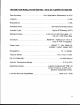
Fluid Sound Speeds Original Date: Revision: Revision Date: File: Fluid Acetate, Butyl (n) Acetate, Ethyl Acetate, Methyl Acetate, Propyl Acetone Alcohol Alcohol, Butyl (n) Alcohol, Ethyl Alcohol, Methyl Alcohol, Propyl (I) Alcohol, Propyl (n) Ammonia (35) Anlline (41) Benzene (29,40,41) Benzol, Ethyl Bromine (21) n-Butane (2) Butyrate, Ethyl Carbon dioxide (26) Carbon tetrachloride Chloro-benezene Chloroform (47) Diethyl ether Diethyl Ketone Diethylene glycol Ethanol Ethyl alcohol Ether Ethyl ether Ethyle
Linseed Oil Methanol (40,41) Methyl alcohol (40,44) Methylene chloride (3) Methylethyl Ketone Motor Oil (SAE 20/30) Octane (23) Oil, Castor Oil, Diesel Oil (Lubricating X200) Oil (Olive) Oil (Peanut) Paraffin Oil Pentane Petroleum 1-Propanol (46) Refrigerant 11 (3,4) Refrigerant 12 (3) Refrigerant 14 (14) Refrigerant 21 (3) Refrigerant 22 (3) Refrigerant 113 (3) Refrigerant 114 (3) Refrigerant 115 (3) Refrigerant C318 (3) Silicone (30 cp) Toluene (16,52) Transformer Oil Trichlorethylene 1,1,1-Trichloro-etha
Ductile Iron Pipe Standard Classes Pipe Outside Size Diameter (inches) (inches) Class 50 Class 51 Class 52 Class 53 Class 54 Class 55 Class 56 ID Wall ID Wall ID Wall ID Wall ID Wall ID Wall ID Wall 0.25 0.26 0.28 0.30 0.32 0.34 3.40 4.22 6.28 8.39 10.40 12.46 0.28 0.29 0.31 0.33 0.35 0.37 3.34 4.16 6.22 8.33 10.34 12.40 0.31 0.32 0.34 0.36 0.38 0.40 3.28 4.10 6.16 8.27 10.28 12.34 0.34 0.35 0.37 0.39 0.41 0.43 3.22 4.04 6.10 8.21 10.22 12.28 0.37 0.38 0.40 0.42 0.44 0.46 3.
Cast Iron Pipe Standard Classes CLASS A Size O.D. (Inches) Inch CLASS B CLASS C CLASS D CLASS E I.D. O.D. Wall Inch Inch I.D. O.D. Wall Inch Inch I.D. O.D. Wall Inch Inch I.D. O.D. Wall Inch Inch CLASS F CLASS G CLASS H I.D. O.D. Wall Inch Inch I.D. O.D. Wall Inch Inch I.D. O.D. Wall Inch Inch I.D. Inch Wall 3 3.80 3.02 0.39 3.96 3.12 0.42 3.96 3.06 0.45 3.96 3.00 0.48 4 4.80 3.96 0.42 5.00 4.10 0.45 5.00 4.04 0.48 5.00 3.96 0.52 6 6.90 6.02 0.44 7.10 6.14 0.48 7.10 6.08 0.
Steel, Stainless Steel, P.V.C. Standard Schedules Nominal OUTSIDE Pipe Size DIAMETER Inches SCH. 5 SCH. 10 (LTWALL) SCH. 20 SCH. 30 ID ID ID Wall ID Wall Wall Wall STD. ID Wall SCH. 40 SCH. 60 ID Wall ID Wall X STG. SCH. 80 SCH. 100 SCH. 120 SCH. 140 SCH. 180 ID ID ID ID Wall 0.815 1.160 1.338 1.687 2.125 2.624 0.250 0.250 0.281 0.344 0.375 0.438 ID Wall ID Wall 1 1.25 1.5 2 2.5 3 1.315 1.660 1.900 2.375 2.875 3.500 1.185 1.530 1.770 2.245 2.709 3.334 0.065 0.
FPS TO GPM CROSS - REFERENCE (Schedule 40) Nominal I.D. Pipe INCH (Inches) 1 1.5 2 2.5 3 3.5 4 4.5 5 5.5 6 6.5 7 7.5 8 8.5 9 1 1.05 2.6989 4.0484 5.3978 6.7473 8.097 9.4462 10.796 12.145 13.490 14.844 16.190 17.540 18.890 20.240 21.590 22.941 24.290 1.25 1.38 4.6620 6.9929 9.3239 11.655 13.99 16.317 18.648 20.979 23.310 25.641 27.970 30.300 32.630 34.960 37.300 39.627 41.958 1.5 1.61 6.3454 9.5182 12.691 15.864 19.04 22.209 25.382 28.555 31.730 34.900 38.070 41.250 44.420 47.
FPS TO GPM CROSS - REFERENCE (Schedule 40) Nominal I.D. Pipe INCH (Inches) 1 1.5 2 2.5 3 3.5 4 4.5 5 5.5 6 6.5 7 7.5 8 8.5 9 18 16.88 697.52 1046.3 1395.0 1743.8 2093.0 2441.3 2790.1 3138.8 3488.0 3836.3 4185.0 4534.0 4883.0 5231.0 5580.0 5928.9 6277.7 20 18.81 866.14 1299.0 1732.0 2165.3 2598.4 3031.5 3464.6 3897.6 4330.7 4763.8 5196.8 5629.9 6063.0 6496.0 6929.1 7362.2 7795.3 24 22.63 1253.7 1880.0 2507.0 3134.1 3761.0 4387.8 5014.6 5641.5 6268.3 6895.1 7522.0 8148.8 8775.6 9402.
GENERAL TERMS AND CONDITIONS OF SALES 1. PAYMENT – Terms of payment are effective from the actual date of invoice. If, in the Seller’s opinion, the financial condition of the Buyer at any time – or any other circumstances – do not justify the incurrence of production costs of shipment on the terms of payment specified, the Seller may require partial or full payment in advance. Payment terms are net 30 days unless otherwise stated on invoice. 2. F.O.B.
Limited Warranty and Disclaimer Dynasonics, div. of Racine Federated Inc. warrants to the end purchaser, for a period of one year from the date of shipment from our factory, that all new transmitters and transducers manufactured by it are free from defects in materials and workmanship. This warranty does not cover products that have been damaged due to normal use, misapplication, abuse, lack of maintenance, or improper installation.
RETURN OF EQUIPMENT/SALES INFORMATION CONTACTS AND PROCEDURES Customer Service/Application Engineer: If you have a question regarding order status, placing an order, reviewing applications for future purchases, or wish to purchase a new flowmeter, please contact our new National Sales and Marketing Headquarters: DYNASONICS Division of Racine Federated, Inc.
8635 WASHINGTON AVENUE RACINE, WI 53406 TOLL-FREE IN NORTH AMERICA.: TEL: (800) 535-3569 FAX: (800) 732-8354 TEL: (262) 639-6770 FAX: (262) 639-2267 URL: www.dynasonics.