® Water Flow Meter Installation and Operating Instructions
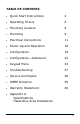
TABLE OF CONTENTS Quick Start Instructions 4 Operating Theory 6 Mounting Location 8 Plumbing 9 Electrical Connections 11 Power-Up and Operation 18 Configuration 19 Configuration—Advanced 24 Keypad Menu 34 Troubleshooting 37 Service and Repair 38 WEEE Directive 39 Warranty Statement 40 Appendix A Specifications Hazardous Area Installation 3
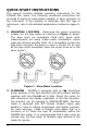
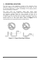
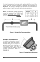
QUICK-START INSTRUCTIONS This manual contains detailed operating instructions for the FUSION flow meter. The following condensed instructions are provided to assist an experienced operator in basic operation of the instrument. If the operator is unfamiliar with this type of instrument, refer to the detailed explanations located on pages 932. 1. MOUNTING LOCATION Determine the proper mounting location for the flow meter by referring to Figure 1 below.
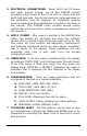
3. ELECTRICAL CONNECTIONS Route 12-30 volt DC power and earth ground through one of the FUSION conduit connections and secure at the 12-30 VDC In, Power Gnd and Earth Gnd terminals. Ensure that electrical codes applicable to the installation area are followed. An installation drawing covering Hazardous Area installations is located in the back of this manual. (The FUSION meter contains several output options that will be covered in detail in subsequent sections of this manual.) 4.
OPERATING THEORY The FUSION ultrasonic flow meter is designed to measure volumetric flow of clean, solids-bearing or aerated liquid on full pipes. There are no moving parts to jam or wear and the product cannot be damaged by gas pockets, particulate or high flowing conditions. The unit contains several input/output options for integration with monitoring and control systems.
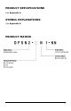
PRODUCT SPECIFICATIONS See Appendix A. SYMBOL EXPLANATIONS See Appendix A.
1. MOUNTING LOCATION The first step in the installation process is the selection of an optimum location for the flow measurement to be made. For this to be done effectively, a basic knowledge of the piping system and its plumbing is required. The pipe must be completely filled with liquid while measurements are being made—avoid installations where pipes can become partially filled for long periods of time.
2. PLUMBING FUSION is equipped with an IN directional arrow pointing in the flow direction that will produce positive readings with the FLO DIR set to POS. Mount the meter for best viewing of the display regardless of the flow direction; the direction can be changed in CONFIGURATION (see page 22). If flow through the system is in the direction of the IN arrow, the FLO DIR should be set to POS. If flow through the system is opposing the IN arrow, the FLO DIR should be set to NEG.
For best measurement accuracy and reading stability, mount the meter with the minimum lengths of straight pipe described in Figure 4. The optimum straight pipe diameter recommendations apply to pipes in both horizontal and vertical orientation. Note: If adequate straight plumbing cannot be provided, the FUSION will operate repeatably and reliably, but will not achieve optimum accuracy.
3. ELECTRICAL CONNECTIONS The FUSION flow meter is equipped with three threaded conduit holes located on the bottom of the flow meter enclosure that are suitable for routing of field wiring. A sealed cord grip or sealed threaded conduit connection should be utilized to retain the NEMA 4 integrity of the flow meter enclosure. Failure to do so will void the manufacturer’s warranty and can lead to product failure.
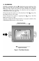
POWER CONNECTIONS Power for the FUSION flow meter is obtained from a DC (direct current) power source. The power source should be capable of supplying between 12 and 30 Vdc at a minimum of 0.1 Amps or 100 milliamps. With the power from the DC power source disabled or disconnected, connect the positive supply wire and ground to the appropriate field wiring terminals in the flow meter. See Figure 7. A wiring diagram decal is located adjacent to the field wiring terminals within the FUSION enclosure.
4-20mA CONNECTION The FUSION is equipped with a ground-referenced 4-20 mA output—the output shares a common ground with the power supply. The output transmits a continuous current output that is proportional to liquid flow rate. The output was scaled at the Dynasonics factory and the scaling information is recorded on the label located outside of the FUSION enclosure.
The 4-20 mA output is designed to source current across a loop resistance that is typically located within a data acquisition system or other receiving instrument. The maximum resistance that the FUSION can accommodate is directly related to the DC power source that is powering the flow meter and the 4-20 mA loop. Figure 8 illustrates the range of load resistance that can be used with a given power supply voltage.
RATE PULSE OUTPUT The FUSION is equipped with an open-collector transistor circuit that outputs a pulse waveform that varies proportionally with flow rate—from 0 Hz at zero flow rate to 1,000 Hz at full flow rate (configuration entry FULL FLOW described in detail in the flow meter configuration section of this manual). To ensure that accurate readings are being recorded by the receiving instrument, the FUSION and the receiving instrument must have identical K-factor values programmed into them.
Rate Pulse Output Connection Figure 10 illustrates the field wiring terminals and switch settings utilized for the rate pulse output. Full Flow / K-factor Calculation The Rate Pulse output generates 1,000 Hz (pulses per second) at full flow. To adjust the K-factor of the meter, adjust the full flow entry. Two examples of this conversion are listed below.
TOTAL PULSE OUTPUT The FUSION is equipped with an open-collector transistor circuit that outputs a 33 millisecond pulse each time the flow meter totalizer display increments—i.e., one pulse for every gallon or barrel. Adjustment of the Total Unit and Total Exponent parameters influences the frequency of the total pulse output.
4. FUSION POWER-UP FUSION Firmware Version After power is applied to the FUSION flow meter, the display will illuminate and show the software version that is running inside of the flow meter as Ux.xx. Have the firmware version available when contacting factory technical support personnel so that more effective service can be provided. Initialization After power-up or after exiting Keypad Configuration, the flow meter will conduct self-diagnostic, measurement and buffering operations.
6. CONFIGURATION The FUSION meter has two basic sets of programming procedures: List Item Selection and Numeric Value Entry. It also has two configuration menus—Basic and Advanced. IMPORTANT: The FUSION software is structured using two menus—a Basic menu and an Advanced menu. Pressing the MENU key for less than three seconds places the user into the Basic menu. Pressing and holding the MENU key for more than three seconds will place the user into the Advanced menu.
Numeric Value Entry Procedure Note: If you are already in PROGRAM mode and the selection to be viewed or changed is already displayed, proceed to step 3 below. If you are in PROGRAM mode and the selection to be viewed or changed is not displayed, press the ▲ or ► arrow keys and repeat pressing until the desired selection appears. Proceed to step 3. 1. Press MENU key. 2. Press the ► arrow key to move to the desired selection.
MENU key, press key to step through setup. Press ENTER to edit a value. Press ENTER to save a value. RATE UNIT GPM M3/H BPD LPM TOTAL UNIT GAL M3 BBL LIT FLOW DIR POS NEG FULL FLOW 0-9999 Rate Unit FLOW C-OFF 0-999.9 Rate Unit OUTPUT NONE 4-20MA PULSE RESPONSE FAST MED SLO Press MENU to exit. RATE UNT -- Engineering Units for Flow Rate GPM—Gallons per minute LPM—Liters per minute BPD—Barrels per days (42 U.S. gallons) M3/H—Cubic meters per hour 1.
FLO DIR -- Flow Direction POS - Normal Flow Direction NEG - Reverse Flow Direction Corrects (shows positive flow) display and outputs if flow is running backwards through the FUSION meter. If flow through the system is in the direction of the IN arrow, the FLO DIR should be set to POS. If flow through the system is opposing the IN arrow, the FLO DIR should be set to NEG. 1. To change flow direction, press the MENU key. 2. Press the ► key to display FLO DIR on bottom display. Press the ENTER key. 3.
2. Press the ► key to display FL C-OFF on bottom display. Press the ENTER key. 3. Press the ► key to move one digit right and the ▲ key to increment a flashing digit. Values are entered in flow rate units. 4. Press the ENTER key. 5. Press the MENU key to exit. OUTPUT -- Output Type NONE - 4-20mA and Rate Pulse Outputs disabled 4-20MA - 4-20mA Analog Output RATE - Rate Pulse Output (0-1,000 Hz) Utilized to select either the 4-20mA or 1,000 Hz rate pulse output. 1.
RATE TST -- Rate Pulse Output Test Allows a fixed frequency to be output from the rate pulse output. By incrementing this value, the rate pulse output will transmit the indicated frequency. The RATE TEST prompt only appears if the output is configured for Pulse output. The output will be spanned between 0 flow and the value entered for Full Flow Rate. Select the rate tst feature. Use the ▲ and ► keys to increment/ decrement output frequency.
ID INCH -- Pipe Inside Diameter Entry 0.5 (Inches) 1.0 (Inches) 2.0 (Inches) Select the appropriate transducer size. DISPLAY -- Display Mode Selection RATE TT Diag (transit time diagnostics) DOP DIAG (Doppler Diagnostics) To display only the Flow Rate and Total, select RATE. Diagnostic display modes are explained in the troubleshooting section. The TT diagnostics selection places the display in the transit time diagnostics mode.
TOTAL OP -- Total Operation POS - Accumulates when flow direction is positive only. NET - Adds or Subtracts from Total depending upon flow direction. Applies to transit time mode only. SET TOTAL -- Preset Totalizer Enter the value in user selected total units that the flow meter is to begin totalizing.
Calibration of the 20 mA setting is conducted much the same way as the 4 mA adjustments. Procedure: 1. Disconnect the current loop output and connect the milliammeter in series between the 4-20mA output and the recording device. 2. Using the arrow keys, increase the numerical value to increase the current in the loop to 20 mA. Decrease the value to decrease the current in the loop to 20 mA. Typical values range between 3700-3900 counts. 3. Re-connect the 4-20 mA output connections as required.
AGC MODE—Automatic Gain Control Mode of Operation NORMAL - Standard Configuration MANUAL - AGC disabled Select the desired mode of operation. A basic understanding of the AGC logic is required in order to know when to use any selection other than NORMAL. When the unit is powered up, there is a delay before the unit begins transmitting sound into the pipe. During this time, the signal strength is measured, and a base signal level is obtained. Typically this is a value of about 20.
MEDIUM - (350Hz Cutoff) HIGH - (250Hz Cutoff) Select the hardware filter with a cutoff frequency that is above the Doppler shift frequency to be measured. DRIVE—Transducer Drive Signal Level If the signal strength is higher than normal, or the meter is reading noise at no flow, the drive level may be reduced to obtain a more accurate reading. 0 = Lowest Drive Level 4 = Highest Drive Level ADV TT -- Advance Transit Time Setup Mode Advance setup mode allows access to the following parameters.
4. Press the key to display adv tt on bottom display. Press ENTER key. Press the key to display yes on bottom display. Press ENTER key. 5. At capture 0 display, press ENTER key. Press the key to display yes on bottom display. Press ENTER key. 6. If ERROR is displayed on bottom display, repeat step 5 until successful. 7. Press the MENU key to exit.
BAUD RATE—Modbus communications baud rate 9600 - 9600 Baud 19200 - 19.2K Baud Select the required baud rate from the list. Standard Modbus Implementation A subset of the standard Modbus commands is implemented to provide access into the data and status of the FUSION Meter. The following Modbus commands are implemented: Command Description 04 Read Input Registers 05 Force Single Coil Opcode 04 – Read Input Registers This opcode returns the input registers, such as flow rate or totalizer.
The flow rate is normalized to return 0 for min flow and 65535 for the maximum flow as specified in the system configuration for Full Flow rate. (See page 23.) Command: Reply: <04><00><00><00><01> <04><02> The totalizer returns the displayed value in four 8 bit words.
C Source Code A.1.
Advanced Menu Map 34
Advanced Menu Map 35
Basic Menu Map 36
Troubleshooting Display does not illuminate 1. Check DC voltage at terminal strip. 2. Check display ribbon cable. 3. FUSION meters are equipped with automatic reset fuses. Output does not match displayed flow value 1. Verify that 4-20mA or Rate PULSE is properly selected in the OUTPUT selection. 2. Check full flo span value entry—ensure it matches receiving device. 3. PULSE outputs—verify proper pull-up jumpers are in place. 4. Utilize 4-20mA Test and PULSE test to simulate outputs to receiving devices.
SERVICE AND REPAIR When returning equipment, it is necessary to contact our service department at (800) 535-3569 or (262) 639-6770 to obtain an RGA number for the authority and tracking of your material and its proper inspection and return.
WASTE ELECTRICAL AND ELECTRONIC EQUIPMENT (WEEE) DIRECTIVE In the European Union, this label indicates that this product should not be disposed of with household waste. It should be deposited at an appropriate facility to enable recovery and recycling. For information on how to recycle this product responsibly in your country, please visit: www.racinefed.
STATEMENT OF WARRANTY Dynasonics, a division of Racine Federated Inc. warrants to the end purchaser, for a period of one year from the date of shipment from the factory, that all flow meters manufactured by it are free from defects in materials and workmanship. This warranty does not cover products that have been damaged due to misapplication, abuse, lack of maintenance, modified or improper installation.
APPENDIX A 41
PRODUCT SPECIFICATIONS Description Specification Input Voltage 12-30 VDC @ 100 mA Max; Class 2 Supply Protection Reverse polarity; auto-reset polyfuse; transient voltage suppression Flow Range 1-Inch 0.7—60 GPM [24-2057 BPD] 3-230 LPM [0.18-13.8 M3/H] Accuracy 1% of Rate over the top 10:1 measuring range; 0.1% of full scale at rates less than this range Pressure Temperature 300 PSI [2,070 kPa] -30 to +160 °F [-34 to +70 °C] Outputs (FUSION cannot output 4-20mA and Rate Pulse simultaneously.
SYMBOL EXPLANATIONS ! Caution—Refer to accompanying documents FLOW METER INSTALLATION ! WARNING: EXPLOSION HAZARD - SUBSTITUTION OF COMPONENTS MAY IMPAIR SUITABILITY FOR CLASS I, DIVISION 2 ! IMPORTANT NOTE: Not following instructions properly may impair safety of equipment and/or personnel. ! IMPORTANT NOTE: Must be operated by a Class 2 supply suitable for the location. ! ! IMPORTANT NOTE: Do not connect or disconnect either power or outputs unless the area is known to be nonhazardous.
NOTES 46
8635 Washington Avenue Racine, WI 53406 Toll-Free in U.S. and Canada: Tel: (800) 535-3569 Fax: (800) 732-8354 Tel: (262) 639-6770 Fax: (262) 639-2267 www.dynasonics.com DYNASONICS and FUSION are registered trademarks of Racine Federated Inc. National Electrical Code is a registered trademark of NFPA. UL is a registered trademark of Underwriters Laboratories. 48 © 2011 Racine Federated Inc. All rights reserved.