MODEL UFX ULTRASONIC FLOW METER Operating Instructions 1
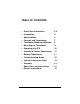
TABLE OF CONTENTS • Quick Start Instructions 4-5 • Introduction 6 • Specifications 6 • Controls and Terminology 7 • Transducer Mounting Locations 8 • Mounting the Transducer 9 • Operating the UFX 10 • Velocity to Volume Conversions 11 • Battery Replacement 11 • Troubleshooting Guide 12 • Velocity Conversion Chart 13 • Warranty 14 • Spare Parts and Accessories 15 • Service Instructions 15 3
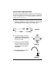
QUICK-START INSTRUCTIONS This manual contains detailed operating instructions for the UFX instrument. The following condensed instructions are provided to assist an experienced operator in basic operation of the instrument. If the operator is unfamiliar with this type of instrument, refer to the detailed explanations located at the corresponding letter on pages 8-11. A. Select a transducer mounting location at least 10 pipe diameters downstream and 5 diameters upstream of flow disturbances (i.e.
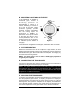
E. Apply approximately ⅛ inch [3 mm] silicone grease to the transducer face. Place the transducer face on the prepared area of pipe. Hold the transducer parallel to the pipe with the cable pointing downstream of the flow direction. STEP E F. Press the ON/OFF key. Wait at least 30 seconds before recording a reading. The UFX will automatically turn itself off after 3 minutes. G. Change units of measure by pressing the FT/SEC M/SEC key.
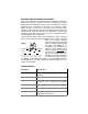
INTRODUCTION AND OPERATING THEORY Series UFX Phase Shift Flow Meters feature advanced Trans-Phase measuring technology, providing accurate and reliable flow velocity assessments in closed piping systems. The UFX utilizes a non-invasive transducer which is hand-held or strapped to the outside of a pipe. Within seconds, the large 0.7 inch [18mm] LCD provides stable readings in either FPS (Feet per Second) or MPS (Meters per Second).
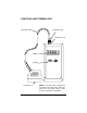
CONTROLS AND TERMINOLOGY Transducer Cable Transducer Plug Transducer Jack Display Keypad Transducer NOTE: The UFX battery compartment is located on the back of the enclosure. Remove the two upper screws to gain access to the battery compartment.
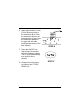
A. TRANSDUCER LOCATION Selecting the proper location for taking a flow measurement is the single most critical step in the operational procedure. The transducer utilized by the UFX flow meter contains two piezoelectric crystals for transmitting and receiving ultrasonic signals through the wall of a pipe. Select a transducer location with adequate straight runs (without flow disturbances) of pipe, both upstream and downstream, to achieve stable and accurate readings.
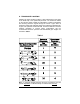
B. MOUNTING LOCATIONS ON THE PIPE If the transducer is applied to horizontal pipe, choose a mounting position at approximately 3 o’clock or 9 o’clock, assuming 12 o’clock to be to top of the pipe. These positions typically provide optimum acoustic penetration into the moving liquid. As illustrated in Figure 2, placement at the top or bottom of the pipe can result in poor sound penetration due to air pockets (on the top of the pipe) or sediment (at the bottom of the pipe).
Apply an even layer of grease, approximately ⅛" (3 mm) thick to the flat surface of the transducer. Place the transducer on the prepared area of the pipe, with the cable pointing downstream. See Figure 3. Align the transducer with the pipe, ensuring that it is parallel with the pipe wall. Apply only enough pressure to hold the transducer in place. If no reading is shown, perform a “rub test” by rubbing thumb across the dry transducer head. The zeros should display a low flow reading.
H. CONVERSION FROM VELOCITY TO VOLUME The velocity readings taken from the UFX can be readily converted to volumetric flow rate measurements such as GPM (gallons per minute) or LPM (liters per minute). A chart is located on page 13 of this manual that contains conversions for many popular schedule 40 pipe sizes. If the pipe size is not located in this chart, use the following equations: ♦ For conversion to GPM (pipe I.D. in inches): GPM = FT/SEC x 2.448 x I.D.2 ♦ For conversion to LPM (pipe I.D.
TROUBLESHOOTING GUIDE Unit does not turn “ON” when ON/OFF key is pressed • Verify that batteries are installed and “Err1” is indicated • The batteries must be replaced. No display readings are obtained and no “OK” icon is observed • Poor acoustic coupling to pipe. Apply contain a charge. silicone grease to transducer. • Ensure pipe is full of a flowing liquid. • If the pipe has a plastic liner, move the transducer to another location. The liner may contain an air void. • Non-working transducer.
LIQUID VELOCITY TO VOLUME CONVERSION CHART 13
STATEMENT OF WARRANTY Dynasonics, Division of Racine Federated Inc. warrants to the end purchaser, for a period of one year from the date of shipment from the factory, that all flow meters manufactured by it are free from defects in materials and workmanship. This warranty does not cover products that have been damaged due to defects caused by misapplication, abuse, lack of maintenance, modified or improper installation.
SPARE PARTS AND ACCESSORIES PART NUMBER DESCRIPTION D002-2007-001 D002-2007-002 D002-2011-002 D002-2011-001 D003-0825-001 DTUFX-D1 DTUFX-B1 DTUFX-D1-CE DTUFX-B1-CE DUFX O&M D003-1009-005 SS Mounting Strap, 36 inch [900 mm] Nylon Mounting Strap, 30 inch [750 mm] Couplant, RTV (for permanent mounting) Couplant, Silicone (for temporary mounting) SS Identification tag Series DUFX Std. Pipe Transducer Series DUFX Small Pipe Transducer Series DUFX Std.
8635 Washington Avenue Racine, WI 53406 Toll-Free in U.S. and Canada: Tel: (800) 535-3569 Fax: (800) 732-8354 Tel: (262) 639-6770 Fax: (262) 639-2267 www.dynasonics.com © 2011 Racine Federated Inc. All rights reserved. Printed in the USA DYNASONICS is a registered trademark of Racine Federated Inc. UL is a registered trademark of Underwriters Laboratories.