Price: $25 US Industrial Fiber Optic Link/Repeaters \ Model CH45 User Manual UMCH45 REV AB 25 Commerce Way #1 North Andover, MA 01845 (978)-688-8807 • FAX (978)-688-8771 www.dymec-dynastar.
Warnings, Cautions, and Notes as Used in this Publication WARNING Warning notices are used in this publication to emphasize that hazardous voltages, currents, or other conditions that could cause personal injury exist in this equipment or may be associated with its use. In situations where inattention could cause either injury or damage to equipment, a Warning notice is used. CAUTION Caution notices are used where equipment malfunction is possible if care is not taken.
Table of Contents Page 1. Introduction . . . . . . . . . . . . . . . . . . . . . . . . . . . . . . . . 1.1 Definitions . . . . . . . . . . . . . . . . . . . . . . . . . . . . . 1.2 Model CH45 Link/Repeater . . . . . . . . . . . . . . . . . . . . . 1.2.1 9 pin Data Port D-Connector . . . . . . . . . . . . . . . . 1.2.2 HD/FD Jumpers . . . . . . . . . . . . . . . . . . . . . . . 1.2.3 Mode Jumpers . . . . . . . . . . . . . . . . . .. . . . . . . 1.2.4 Data Coupling Jumpers . . . . . . . . . . . . . . . . . .
Model CH45 EIA 422 or 485 1. INTRODUCTION The DYMEC-DynaStar Model CH45 is a data communication Link/Repeater Card, for use in the DYMEC-DynaStar 3900 Series Chassis, which allows the replacement of copper wire with fiber optic cable. Link/Repeaters simply convert electrical signals to light for transmission, then, when received, convert the light to electrical signals. This is done for EIA 422 and EIA 485 formats. Link/Repeaters are passive to software protocol.
Model CH45 EIA 422 or 485 Slave: A Slave is an IED that is passive in a Master/Slave configuration. A Slave's communication is under the control of the Master, and the slave only responds to specific poll requests from the Master. Peer: Peers are IEDs that have equal status and each may initiate a communication when allowed by the system software by a time slot, token, etc. FOC: Fiber Optic Cable. Single-mode: Single-mode fibers generally have diameters of 5µm to 13µm.
Model CH45 EIA 422 or 485 Full Duplex Communication: Simultaneous transmit and receive communications. T: Transmit optical port. TE: Diagnostic LED that illuminates when the Link/Repeater is receiving an electrical transmit from its IED. TO: Diagnostic LED that illuminates when the Link/Repeater is transmitting a signal optically. R: Receive optical port. RE: Diagnostic LED that illuminates when the Link/Repeater is delivering a received optical signal electrically to the IED.
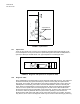
Model CH45 EIA 422 or 485 1.2 MODEL CH45 LINK/REPEATERS Each Link/Repeater consists of the following elements shown in Figure 1. Logic Invert Jum per B iasing R esistor Jum pers H D /FD Jum pers D B 9 Electrical C onnector D iagnostic LE D 's S T Fiber C onnectors R epeat Jum per D ata C oupling Jum pers FIGURE 1. Elements of the Link/Repeater 1.2.1 9 pin Data Port D-connector The Link/Repeater connects directly to an IED's EIA 422 or 485 communication port.
Model CH45 EIA 422 or 485 HD MODE • • • • • • • • • 1 2 3 4 5 6 7 8 9 HD FD FD MODE • • • • • • • • • Trans/Rec Data − [B/B’] Trans/Rec Data + [A/A’] No Connect No Connect Signal Ground No Connect No Connect No Connect Chassis Ground 1 2 3 4 5 6 7 8 9 HD FD Transmitted Data − [B] (Link lnput) Transmitted Data + [A] (Link Input) Received Data − [B’] (Link Output) Received Data + [A’] (Link Output) Signal Ground No Connect No Connect No Connect Chassis Ground FIGURE 2.
Model CH45 EIA 422 or 485 1.2.4 Data Coupling Jumper The Data Coupling jumper selects the electrical input conditioning; the AC position selects capacitively coupled, the DC position is directly coupled. 1.2.5 AC: AC coupling has a minimum incoming data requirement of 1200 baud due to the capacitive coupling. This option blocks DC electrical levels should the device connected fail and ‘stick in a high level’.
Model CH45 EIA 422 or 485 T Optical Port R Optical Port FIGURE 5. Optical Ports 1.2.7 Optical Ports There are two optical ports, T and R. The T optical port transmits data signals optically to the next Link/Repeater. The R port receives the optical data signal from another Link/Repeater's T optical port. Each port is fitted with an "ST" type receptacle for connecting the FOC FIGURE 6. Diagnostic LED positions on faceplate of CH45 1.2.
Model CH45 EIA 422 or 485 that the illumination of the LEDs corresponds with activity in the unit. See Figure 7 for LED patterns and signal paths. 2 1 4 3 2 1 4 3 2 1 REP REP O FF O FF 4 3 REP O FF Norm al Transm ission Norm al Receive Repeat Mode Selected FIGURE 7. Diagnostic LED patterns and signal paths NOTE The diagnostic LEDs only illuminate when there is signal traffic and are not illuminated during signal "quiet" times.
Model CH45 EIA 422 or 485 manufacturer's specification on attenuation per unit length, attenuation due to aging, diameter, and tensile strength. Choosing the best quality FOC for your installation is important. NOTE DYMEC-DynaStar can supply multi-mode glass FOC in either Simplex, Duplex, or Breakout construction, cut to length, terminated, polished and tested. The specifications for all DYMEC-DynaStar supplied cables are as follows: Fiber Diameter: Tensile Strength: Loss: Aging Loss: 62.
Model CH45 EIA 422 or 485 2. CONFIGURATIONS, OPERATION, AND INSTALLATION Model CH45 Link/Repeaters can be connected in a Point-to-Point configuration, an Optical Bus network, an Optical Star network, or a Master/Slave Loop configuration depending on the needs of the overall communication system. Model CH45 is designed to accept differential electrical inputs per EIA 422 and EIA 485 standards. Various implementation of these electrical standards can result in different types of electrical circuits.
Models CH45 EIA 422 or 485 M aster T+ T- 2 1 Last Slave T+ T- R+ R- 4 3 2 1 R+ R- 4 3 R EP R EP OFF OFF FIGURE 8. Point-to-Point Configuration 2.1.1 Installation 1. Set the HD/FD Jumper to the appropriate position for each Link/Repeater and its respective IED. 2. Set the Mode Jumper on both of the units to the "OFF" position. 3. Set the Data Coupling Jumpers for the appropriate position based on the data rate used in the communication network 4.
Model CH45 EIA 422 or 485 NOTE The diagnostic LEDs only illuminate when there is signal traffic and are not illuminated during signal "quiet" times. If during quiet time, TE and TO are illuminated, it suggests either a polarity reversal (pin 2 with pin 1) or that the IED is biased pulling the “A” (+) line with respect to the “B” (-) line. After checking the polarity on the connections, refer to Section 3.5. The diagnostic LEDs may "flicker" when data is passing. This is normal operation.
Models CH45 EIA 422 or 485 Four W ire EIA 485 Master/Slave M aster T+ T- 2 1 Typical Slave T+ T- R+ R- R EP 4 3 2 1 4 3 Last Slave T+ T- R+ R- 2 1 4 3 2 1 R+ R- 4 3 O FF R EP O FF R EP R EP O FF O FF Tw o W ire EIA 485 Master/Slave M aster Typical Slave - + 2 1 - + R EP 2 Last Slave 1 2 - + 1 2 O FF 1 R EP O FF R EP R EP O FF O FF Figure 10. EIA 485 Bus Configurations APPLICATION NOTE Another variation of the point-to-point concept, is the Optical Star network.
Model CH45 EIA 422 or 485 The DYMEC-DynaStar Optical Stars can also be used to create a multi-drop Master / Slave Optical Star network. The Model CH45 is optically compatible with the OS5 and OS9 Master and Slave ports. Figure 11 shows a typical connection of an Optical Star network. The master IED must always be connected to the Master port (port 1) of the Optical Star. The slave IED’s must always be connected to the Slave ports (port 2 and up) of the Optical Star.
Models CH45 EIA 422 or 485 Master IED T R D ym ec M O D EL O S5 F IB ER O PT IC ST AR Slave IED T Slave IED R T Slave IED R T R D ym ec M O D EL O S5 F IB ER O PT IC ST AR Slave IED T Slave IED R T Slave IED R T FIGURE 11.
Model CH45 EIA 422 or 485 2.2 LOOP OPERATION - MASTER/SLAVE CONFIGURATION NOTE Before constructing a loop network, be sure that the software protocol of the Master is capable of managing the receipt of its own echoed transmission. If it cannot, then use either an Optical Bus or Optical Star configuration. This configuration supports a system which requires more than two IEDs to be communicating.
Models CH45 EIA 422 or 485 The Master must have its Mode Jumpers in the "OFF" position. When it transmits a request out its T optical port, it will receive the echo of its request at its R optical port. This request has gone around the loop, and has been repeated by each Slave in the loop. However, the Master does not repeat (retransmit) any of these received signals optically back around the loop, because its Mode Jumpers are in the "OFF" position.
Model CH45 EIA 422 or 485 2.2.1 Installation 1. Set the HD/FD Jumper to the appropriate position for each Link/Repeater and its respective IED. 2. Set the Mode Jumper to “OFF” position on the Master. Set the Mode Jumpers of all the Slave units to the "ON" position. 3. Set the Data Coupling Jumpers for the appropriate position based on the data rate used in the communication network 4. Set the Logic Inversion Jumper to the appropriate position based on the communication network 5.
Models CH45 EIA 422 or 485 3. APPLICATIONS When planning a system using Model CH45 Link/Repeaters, the following considerations should be reviewed: • • • • • • 3.
Models CH45 EIA 422 or 485 3.2.1.2 Fittings Adding additional splices, feed throughs, or patches to the FOC will add losses to the available optical budget. When using multi-mode Fiber Optic Cable terminated and supplied by DYMEC-DynaStar, optical connector losses can be ignored because the cable is tested after the terminations are added. If you are using fittings not supplied by DYMEC-DynaStar, you can get the optical budget loss information from their manufacturer(s). 3.2.1.
Models CH45 EIA 422 or 485 N u m b e r o f R e p e a ts in a L o o p C o n fig u ra tio n * 1000 Repeats 100 10 * 65oC Amb. – 70% of original pulse width 1 1 10 100 1000 D a ta R a te s (k b p s ) FIGURE 13. Number of Repeats 3.3.1 Effects of Data Rate The number of repeaters is an inverse linear function to the data rate (more repeats at lower data rates). The data rate, or bits per second rate, determines what the original pulse width of each bit will be.
Models CH45 EIA 422 or 485 % of Original Pulse 80% 60% 50% 3.3.3 Multiply Factor .67 1.33 1.67 Table 2 Temperature Effect At peak operating temperatures above 65°C, the maximum number of repeats should be de-rated by 20%. At higher temperatures the distortion caused by each repeat increases, causing the maximum number of possible repeaters to go down. EXAMPLE: Peak temperature of the system will be 70°C Running at 9600 bps 60% of original pulse width possible initial: less: times: equals: 3.
Models CH45 EIA 422 or 485 In addition, one can connect DYMEC-DynaStar Models CH43, 5843 or 5844 (RS-232 Link / Repeaters) to the Models CH45, 5845 or 5846 and achieve RS-232 to EIA 422 or 485 format conversion directly in the fiber connection without the need of external converter devices. However, the following condition must be accounted for. In RS-232, the logic state is inverse to the physical layer, i.e. a logic high produces a physical low.
Models CH45 EIA 422 or 485 Point-to-Point: (Mode Jumpers "OFF") Master/Save Loop: Master (Mode Jumpers "OFF") Master/Slave Loop: Slave (Mode Jumpers "REP") 3.10 HD/FD Jumpers in FD Position HD/FD Jumpers in HD Position Simplex Half Duplex Full Duplex Simplex Half Duplex X X X X X X X X X X X X X X Full Duplex SELECTION OF FIBER OPTIC CABLE (FOC) Fiber optical cable is available in several construction types; simplex, duplex, and breakout.
Models CH45 EIA 422 or 485 4. TESTING AND TROUBLE SHOOTING 4.1 TESTING Model CH45 Link/Repeater is easily tested. Testing the unit requires transmitting and receiving data while observing that the diagnostic LEDs are illuminating in the proper sequence. To test whether a unit is transmitting and receiving correctly, set the FD/HD Jumpers to the FD position.
Models CH45 EIA 422 or 485 5. Are the FD/HD Jumpers, the Repeat Jumpers, and NORM / INVERT Jumpers set to the proper position for the application? (Are all four FD / HD Jumpers set to the same position?) NOTE If the Link/Repeater is not connected directly to an IED, determine that the electrical signal received by the Link/Repeater is not corrupt. The Link/Repeater only repeats the signal it is given, it does not re-clock or re-generate the signal. 6. Review the IED's software and protocols.
5. SPECIFICATIONS Electrical and Optical Specifications (All Specifications over entire Operating Temperature Range) Models CH45 LINK: I/O Data Format Configuration EIA 422 or 485 Half/Full Duplex, Jumpers Link/Repeater, Jumpers Input Bias, Jumpers Data Coupling, Jumpers Logic Invert, Jumpers Electrical Connector 9 pin D-type, female Data Rate Data Transmission DC to 2M bps Asynchronous, simplex or full/half duplex up to 5000 m (62.5/125µm cable @ 3dB/km) 10E-9 max.
Mechanical Dimensions of the CH45 5.10 (12.95) 4.81 (12.21) R T CH45 ø.104 2X ALTERNATE MATING CONNECTOR: MOLEX P/N 8981-04M 5.2 LED IND. DB-9 FEMALE CONNECTOR 0.55 (1.39) .99 0.41 "ST" (1.04) (2.51) OPTICS .06 (0.15) 5.0 (12.70) 0.60 (1.52) 1.04 0.4 (2.64) 0.5 (1.27) 1.54 (3.91) 2.60 (6.60) 3.94 (10.00) DIMENSIONS ARE IN INCHES (CENTIMETER) 5-1 (1.
6.
READER'S COMMENTS We invite your comments and welcome suggestions to make this manual more useful. Bulletin # Rev # Today's Date GENERAL COMMENTS: Improve Acceptable Good Excellent Contents Organization Accuracy Clarity Completeness Example/Illustrations Referencing/Indexing Readability DETAILED COMMENTS: (Please be specific; i.e.: correct, expand, etc. ) Page No.