Air_US_rev_111.
Air_US_rev_111.
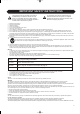
Air_US_rev_111.qxd 16-12-2004 14:14 Page a IMPORTANT SAFETY INSTRUCTIONS The lightning flash with an arrowhead symbol within an equilateral triangle, is intended to alert the user to the presence of uninsulated “dangerous voltage” within the product’s enclosure that may be of sufficient magnitude to constitute a risk of electric shock to persons.
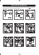
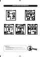
Air_US_rev_111.qxd 16-12-2004 14:15 Page b QUICK SETUP REFERENCE This page is a quick guide on how to connect different setups. Connections must be made exactly as illustrated. Detailed descriptions of the setups can be found on pages 8-16.
Air_US_rev_111.qxd 16-12-2004 14:15 Page c QUICK SETUP REFERENCE Important ! • One specific Master monitor must be set as System Controller. (see setup illustrations above) • To set a Master monitor as System Controller the TC LINK button on the rear panel must be left out. • The TC LINK button on all other Master monitors must be set to In position.
Air_US_rev_111.qxd 16-12-2004 14:15 Page 4 TABLE OF CONTENTS Basics The AIR REMOTE Important Safety Instructions . . . . . . . . . . . . . .a Quick Setup Reference . . . . . . . . . . . . . . . . .b-c Table of Contents . . . . . . . . . . . . . . . . . . . . . . .4 Overview . . . . . . . . . . . . . . . . . . . . . . . . . . . .44 Functions . . . . . . . . . . . . . . . . . . . . . . . . . . . .45 The AIR SOFT Introduction This Manual . . . . . . . . . . . . . . . . . . . . . . . . . . .
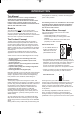
Air_US_rev_111.qxd 16-12-2004 14:15 Page 5 INTRODUCTION This Manual The latest manual revision is always available for download from www.dynaudioacoustics.com The revision number of this manual is located at the bottom of page 4. Please compare to the revision number of the manual available for download from our web-site and download if newer. Break in Your AIR monitors must be “run in” before optimal performance is achieved.
Air_US_rev_111.qxd 16-12-2004 14:15 Page 6 INTRODUCTION The Master Unit The Master unit distributes Audio and control data to the respective Slave units connected. System Controller, Master or Slave To set up a Master unit to be either System Controller or Master/Slave the LINK switch on the rear panel must be set up correctly. Additional AIR Control units Any additional control units, such as the optional AIR Soft Remote or the AIR Remote, can be connected to any free "Link" connector in the system.
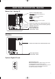
Air_US_rev_111.qxd 16-12-2004 14:15 Page 7 REAR PANEL DESCRIPTION - MASTER Master Unit - Analog I/O • System Controller/Slave switch Out-position :The monitor operates as a System Controller There can be only one System Controller in a setup. In -position: The monitor operates as either a regular Master or a Slave unit. • • • • • • RJ45 Link connections for downstream Slave units Option slot with analog I/O card installed.
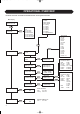
Air_US_rev_111.qxd 16-12-2004 14:15 Page 8 OPERATIONAL OVERVIEW Parameter structure accessible via the AIR monitor set as System Controller Empty Custom Stereo analog Stereo digital 5.1 analog 5.1 digital 6.1 analog 6.1 digital 5.3 analog 5.3 digital 5.1 digital/6 Master Main Display 7854010 L Front Volume -50.
Air_US_rev_111.qxd 16-12-2004 14:15 Page 9 THE AIR DISPLAY & SETTING UP Overload Indication EXIT UP ENTER DOWN ENTER key The ENTER key has two main functions: • To enter the menus currently displayed. • To set the displayed parameter in Edit mode. When a parameter can be edited via the CURSOR keys a “*” is set as the first character in front of the parameter. EXIT key The EXIT key is used to exit the current display and go to previous menu level.
Air_US_rev_111.qxd 16-12-2004 14:15 Page 10 SETUPS Stereo Setup To set a Master monitor as System Controller the TC Link button on the rear panel MUST be in out-position. This illustration shows how to connect a standard stereo setup. • Left monitor is set as System Controller by leaving out the TC Link button on the rear panel. • Left monitor receives both Left and Right Input signal. • Right monitor receives audio via the TC-LINK RJ-45 connection.
Air_US_rev_111.qxd 16-12-2004 14:15 Page 11 SETUPS To set a Master monitor as System Controller the TC Link button on the rear panel MUST be in out-position. 5.1 Digital Setup This illustration shows how to connect a 5.1 digital setup • Left monitor is set as System Controller by leaving out the TC Link button on the rear panel. • Left monitor receives both Left and Right Input signal. Right channel is fed via the TC -LINK RJ-45 connection from the Left to Right.
Air_US_rev_111.qxd 16-12-2004 14:16 Page 12 SETUPS 5.3 Digital Setup To set a Master monitor as System Controller the TC Link button on the rear panel MUST be in out-position. This illustration shows how to connect a 5.3 Digital setup • Center is set as System Controller by leaving out the TC Link button on the rear panel. • Left monitor receives both Left and LS signal. The LS monitor is fed via the TC LINK RJ-45 connection form Left to LS. • Center monitor receives both Center and LFE signal.
Air_US_rev_111.qxd 16-12-2004 14:16 Page 13 SETUPS 6.1 Analog Setup To set a Master monitor as System Controller the TC Link button on the rear panel MUST be in out-position. This illustration shows how to connect a 6.1 Analog setup • Left is set as System Controller by leaving out the TC Link button on the rear panel. • Left monitor receives both the Left and Right signal. The Right monitor is fed via the TC LINK RJ-45 connection form Left to Right.
Air_US_rev_111.qxd 16-12-2004 14:16 Page 14 SETUPS Stereo Setup With Chains on L & R To set a Master monitor as System Controller the TC Link button on the rear panel MUST be in out-position. This illustration shows how to connect a stereo setup with chains on Left and Right. The chained monitors are fed with the same signal as the front L&R monitors. This the type of setup you would use when you wiish to be able to alternate between a set of main- and nearfiels -monitors.
Air_US_rev_111.qxd 16-12-2004 14:16 Page 15 SETUPS 5.1 Digital - 192 kHz To set a Master monitor as System Controller the TC Link button on the rear panel MUST be in out-position. This is a 5.1 digital setup at 192kHz with Bass Management as an option. The setup requires three Master monitors with the optional Digital I/O card installed, two Slaves and one Sub. • Left monitor is set as System Controller by leaving out the TC Link button on the rear panel.
Air_US_rev_111.qxd 16-12-2004 14:16 Page 16 SETUPS 5.3 Digital Setup To set a Master monitor as System Controller the TC Link button on rear panel MUST be in out-position. 16 This illustration shows how to connect a 5.3 Digital setup with Bass management as an option. The setup requires three Master monitors with the optional Digital AES/EBU I/O card installed, two Slave monitors (or Masters set as Slave) and three Subs.
Air_US_rev_111.qxd 16-12-2004 14:16 Page 17 WHEN THE MONITORS ARE CONNECTED This is a simple step by step setup guide Go to Setup menu Overview 1 2 3 4 5 6 7 8 9 Move to: press: Connect the monitors Set one Master monitor as System Controller Turn down volume Set Bass Management off Select Set up menu Clear entire network Select set up (Stereo analog, 5.1 digital, etc) Select monitor tasks (e.g. “L Front”,“Center”, Set Clock Source Connect the monitors Power... Audio... Network...
Air_US_rev_111.qxd 16-12-2004 14:16 Page 18 PARAMETER DESCRIPTION Basic operation in all menus • Use ARROW keys to select value or submenu • Use ENTER to enter menus or for confirmation, and to activate • Use EXIT to step to a higher level or to decline an operation • Values are marked with an “ * “ when they can be altered via the ARROW keys Main Display The Main Display indicates the position of the monitor (when set up) and the set volume for the monitor.
Air_US_rev_111.qxd 16-12-2004 14:16 Page 19 PARAMETER DESCRIPTION Setup Menu • Press ENTER to access sub-menus Set Monitor Task For the System Controller - Master monitor to identify and operate all monitors in the setup, each monitor must be given one of the following tasks indicating function and position. Setup • Press ENTER to enter select mode.
Air_US_rev_111.qxd 16-12-2004 14:16 Page 20 PARAMETER DESCRIPTION Parameters available for AIR 6 and AIR 15 Pink Noise: Range: On/Off Calibrate: Range: -6dB to +6dB Level calibration of the selected monitor. Rel. Lev: Range: -40dB to 0dB Relative preset volume for the selected monitor. Room Position: Neutral Wall Corner Console C. Wall - Console Wall C.
Air_US_rev_111.qxd 16-12-2004 14:16 Page 21 PLACING THE MONITORS This manual section is split into two. The first part is a direct guide on how to optimize your listening facilities to ensure optimal performance of your AIR monitor system. The second part contains In Depth explanations and background information of various acoustic phenomena’s and is referred to on several occasions in the first chapter.
Air_US_rev_111.qxd 16-12-2004 14:16 Page 22 PLACING THE MONITORS Placement of monitors and acoustics do influence monitor sound. AIR series provides powerful tools to compensate for different placement. Below, please find a description of the most common monitor placements and appropriate compensation. Using material from the calibration CD together with the AIR placement compensation settings could help the interaction between the AIR monitor and acoustics the studio.
Air_US_rev_111.qxd 16-12-2004 14:16 Page 23 CHECKING - THE PLACEMENT OF THE MONITORS Overview 1 2 3 4 5 In the Setup menu: Select setup type (e.g. 5.
Air_US_rev_111.qxd 16-12-2004 14:16 Page 24 CHECKING - PLACEMENT OF THE MONITORS Equalizing The AIR System menu offers a two-band shelving type equalizer. This can be used individually on each monitor, and it is implemented for a fine adjustment of the tonal balance. Range: Adjustment step: Band I: Band II: Filter type: ±6 dB 0.5 dB 100 Hz - 1 kHz 1 kHz - 5 kHz Shelving You should be very careful using this tool if you are doing the adjustment by ear.
Air_US_rev_111.qxd 16-12-2004 14:17 Page 25 CALIBRATING Overview 1 2 X-CURVES MAIN MONITORS Select Setup menu from the Main menu - then Calibrate monitor Select each monitor and set calibration level using the CD Calibration procedure The calibration has to be made to ensure that all monitors produce the same sound pressure level in the listening position when fed with the same signal. The level of the input signal can be locked to a specific sound pressure produced by the monitors.
Air_US_rev_111.
Air_US_rev_111.qxd 16-12-2004 14:17 Page 27 CHECKING - SUBWOOFER PLACEMENT Do not place the subwoofer on these lines quarter or halfway between walls. Overview 1 2 3 4 5 Main menu, set volume -20 dB Main menu, select Bass Management: 120 Hz Set Bass Management to “on” Check the monitor position using the CD, tracks 30-44 Go to: Calibrating the subwoofer with the main system.
Air_US_rev_111.qxd 16-12-2004 14:17 Page 28 CALIBRATING THE SUBWOOFER Bass Management Bass management (sometimes called bass redirection) is a very important and useful tool - and it is in general an absolute necessity if you want to make a 5-channel set-up in a small room! There are several reasons for this. The bass management system is designed to subtract the bass contents of all main channels and reproduce this by the use of a sub woofer.
Air_US_rev_111.qxd 16-12-2004 14:17 Page 29 CALIBRATING THE SUBWOOFER LFE Gain Range: 0 to +14dB The LFE channel can be boosted up to 18dB using this parameter. Polarity Range: 0 or 180º If the Subwoofer is correctly placed, setting the Polarity parameter at 180º should result in a full Phase cancellation at the set Cross -over frequency. If this is not the case - the Phase parameter described below should be adjusted.
Air_US_rev_111.qxd 16-12-2004 14:17 Page 30 ACOUSTICS - BACKGROUND INFO Acoustics When we talk about making a room "sound right", we are probably dealing with room acoustics as a science acoustics has been around for about hundred years. Until then good acoustics happened by experiment, by experience, or simply by accident. Today we know a lot about the parameters that influence the "sound" of a room. Talking about the control room we know that basically this room should act as neutral as possible.
Air_US_rev_111.qxd 16-12-2004 14:17 Page 31 ACOUSTICS - BACKGROUND INFO Sabines formula Sabine is the father of modern acoustics. He found that reverberation time is described by a relationship between the room size and the amount of absorption in the room. Larger rooms - longer reverberation. More absorption shorter reverberation. T = 0.161 * V / A where T: V: A: 0.
Air_US_rev_111.qxd 16-12-2004 14:17 Page 32 ACOUSTICS - BACKGROUND INFO Absorbers Diffusers All materials in the room act acoustically even if they are not so-called acoustical materials. Basically we have three kinds of absorbers. A diffuser provides diffuse reflection of the sound radiated against it. It can be a very useful solution in cases where reflections are disturbing the sound image and it is not advisory to ad further absorption. So in order to reduce flutter echoes, comb filtering etc.
Air_US_rev_111.qxd 16-12-2004 14:17 Page 33 BACKGROUND INFO - ACOUSTICS Standing Waves Standing waves exist in all kind of rooms. The shape of the room, the dimensions of the room, and the relationship between the dimensions of the room, are important parameters that will determine the frequencies around which the phenomenon exists as well as the distribution of these standing waves. But how do they occur? Imagine a sound source.
Air_US_rev_111.qxd 16-12-2004 14:17 Page 34 ACOUSTICS - BACKGROUND INFO Room modes These special frequencies are also called room modes. Standing waves between parallel walls are called axial modes. Other modes exist. For instance tangential and radial modes. (See the illustration). Normally the axial modes are the strongest.
Air_US_rev_111.qxd 16-12-2004 14:17 Page 35 ACOUSTICS - BACKGROUND INFO The standing waves are characterized by having a maximum sound pressure at the boundaries of the room. Depending on the frequency there are one or more dips across the room. In a box shaped room the frequencies can be calculated as follows: f= where f = c = l = w= h= n= c n n n ( l )+ ( b )+ ( h ) 2 l w h frequency in Hz speed of sound (approx.
Air_US_rev_111.qxd 16-12-2004 14:17 Page 36 ACOUSTICS - BACKGROUND INFO At low frequencies a monitor can be considered as to radiate the sound energy in all directions. This is also called a 4 π radiation. When placing the monitor close to a solid boundary - for instance a wall - the sound energy that should have been radiated in the direction of the wall instead is radiated into the free half space. Hence the sound pressure is doubled in the half space, which yields +6 dB.
Air_US_rev_111.qxd 16-12-2004 14:18 Page 37 ACOUSTICS - BACKGROUND INFO Comb Filtering The filtering function that arises when a signal is added to itself after having been delayed in time is called a comb filter. The resulting frequency response resembles a comb, hence the name. Two 500 Hz sinusoidal tones added. The second tone is delayed 1 ms hence the sum is zero Two 1 kHz sinusoidal tones added. The second tone is delayed 1 ms hence the sum is the double (+6 dB).
Air_US_rev_111.qxd 16-12-2004 14:18 Page 38 ACOUSTICS - BACKGROUND INFO or + Two typical situations in which comb filters arise, either acoustically or electrically. In general: All digital signal processing takes time. This means in practice that comb filter effects can arise if you loop a signal via, for example, a compressor and combine this signal with the original.
Air_US_rev_111.qxd 16-12-2004 14:18 Page 39 ACOUSTICS - BACKGROUND INFO Rear wall cancellation When the monitor is set up at some distance in front of a wall, reflections from the wall may occur and influence the perceived frequency response. This could result in comb filtering if all frequencies produced by the monitor were radiated in all directions. But the monitors are typically only omni-directional at low frequencies.
Air_US_rev_111.qxd 16-12-2004 14:18 Page 40 THE SUBWOOFER - BACKGROUND INFO The Subwoofer A subwoofer is a monitor that reproduces low frequencies. The purpose is to take over from the main monitor(s) as frequencies approach the lower end of the frequency range. I.e. approximately below 120 Hz. When used in professional monitor systems it is commonly preferred to use subwoofers below approximately 80 Hz. But of course it depends on the performance of the main monitors.
Air_US_rev_111.qxd 16-12-2004 14:18 Page 41 THE SUBWOOFER & LFE CHANNEL - BACKGROUND INFO Checking summing phase cancellation In a basic 2-channel set-up or 5-channel set-up (like the ITU-775) a sub-woofer is not specified and is not required. But making audio production to be played back on consumer equipment, one has to ensure that the mix will sound right in this situation. Many consumer set-ups provide a sub woofer. Hence it is very important to check what the summing of the bass is like.
Air_US_rev_111.qxd 16-12-2004 14:18 Page 42 DELAYING MONITORS ITU 775 When using a 5.x set-up with monitors arranged on a circle line (as with ITU 775) the distance from the listener to each of the main monitors is the same. In case of limited space the three front monitors can be arranged on a straight line. To compensate the center monitor being closer to the listener than the left and right monitor, the center signal can be delayed.
Air_US_rev_111.qxd 16-12-2004 14:18 Page 43 LINE-UP & CALIBRATION - BACKGROUND INFO Calibration of 5.1 in an ITU-775 arrangement In a 5.1 system based on the ITU arrangement, all main channels have in principle the same conditions: there is one monitor per channel and each is placed the same distance from the listener. Internationally, there is however neither agreement on the level nor on the bandwidth for the noise signals that is used for acoustic calibration.
Air_US_rev_111.qxd 16-12-2004 14:18 Page 44 THE AIR REMOTE Introduction When perfect setup and calibrations is in place, optimal performance from the AIR system monitors is achieved by controlling level on the monitors themselves as opposed to controlling via the mixing console. Therefore a remote control is a natural extension to the AIR monitor system. Remote Control Features • Instant access of three different user defined Reference Level settings.
Air_US_rev_111.qxd 16-12-2004 14:18 Page 45 THE AIR REMOTE REF LEVEL 1-3 keys To recall Reference Level 1-3: Press relevant key shortly. The key LED indicates activated Reference Level. To set Reference Level 1-3: Set level using the large VOLUME dialer in the center of the remote. Press and hold relevant Reference level key for approx. 2 seconds. The LED will flash 3 times and then the new Reference level is set.
Air_US_rev_111.qxd 16-12-2004 14:18 Page 46 AIR SOFT The AIR SOFT is a software editor for the AIR System monitors. All parameters controllable via the display locally on the System Controller, as well as the Reference Level features available via the AIR Remote can be controlled via the AIR Soft program. As your AIR monitors most likely are placed out of your immediate reach we are therefore convinced that you will benefit from having full control over your monitor system from your PC or Mac.
Air_US_rev_111.qxd 16-12-2004 14:18 Page 47 AIR SOFT Main Bass Mgt - Bass Management Indicates the selected Cross-over frequency for Bass Management. Tools When placing the cursor on top of a monitor, a few tools will appear: • • • Press this symbol to enter calibration pages Press to solo the monitor Press to mute the monitor This is the Main screen from where all other AIR SOFT screens are accessed.
Air_US_rev_111.qxd 16-12-2004 14:18 Page 48 AIR SOFT Preset List Network Is accessed by clicking on the left side of the display frame. Accessing the Network Screen Press the (((•))) icon in the Main screen to access the Network facilities. In this screen various global network settings are handled.
Air_US_rev_111.qxd 16-12-2004 14:18 Page 49 AIR SOFT During Software upload various messages could be displayed: Example: In a 5.1 AIR setup you are uploading monitor software to the entire system. As there are separate software files for monitors and subs the following message should appear. Monitor assignment Task • Press monitor symbol to activate pink noise test-tone. • Then select task for the monitor now playing the noise. Serial number and type will be indicated.
Air_US_rev_111.qxd 16-12-2004 14:18 Page 50 AIR SOFT Calibrated Level Level calibration of the selected monitor. Polarity Range: 0 or 180 deg. Mark to activate. Relative Level Preset volume for the selected monitor relative to the calibrated and global volume. Calibrated Level Level calibration of the selected monitor. Use Parametric EQ This will be marked if the Parametric EQ is activated via the PC-IP. Bass and Treble settings will be disabled.
Air_US_rev_111.qxd 16-12-2004 14:18 Page 51 MISCELLANEOUS The AIR series are unquestionably high quality products. This section puts focus on a few technical issues that adds to the perception of the products high standard. High efficiency compact Switched Mode Power Supply (SMPS) For saving overhead power consumption and to insure optimal performance disregarding the mains voltage, the unit is equipped with a high efficiency compact Switched Mode Power Supply (SMPS).
Air_US_rev_111.qxd 16-12-2004 14:18 Page 52 CABLES TC LINK Standard Cat-5 cables Maximum Cable Length : 15 meter. Cable type : Shielded Ethernet Cable Category 5. Connector type : RJ45 This connection is carrying Digital audio (24 bit) and network control information. Serial to Cat-5 cable P1 P1 1 2 3 4 5 6 7 8 P2 1 2 3 4 5 6 7 8 - included with the AIR SOFT and PC-IP.
Air_US_rev_111.qxd 16-12-2004 14:18 Page 53 AIR TECHNICAL SPECIFICATIONS AIR 6 & AIR 15 (Master and Slave) Mains voltage Power consumption AIR 6 Two-way Active Nearfield Monitor 40 Hz – 22 kHz > 128 dB peak > 126 dB peak 104 dB RMS +/- 0.2 dB 45 Hz 12.1 liters Bass reflex 2150 Hz (DSP generated) 24 dB/oct (Linkwitz Riley, DSP generated) Esotec 28 mm / 1.1" soft dome, rear chamber, magnetic fluid, 4mm die-cast alu front, pure alu wire voice coil 175 mm / 6.
Air_US_rev_111.qxd 16-12-2004 14:18 Page 54 AIR TECHNICAL SPECIFICATIONS AIR Base-1 & AIR Base-2 System: Total frequency response: Max. SPL 1m, one (IEC Short Term) Max. SPL 2m, 5.1 (IEC Short Term) Precision of monitor matching: Port tuning frequency: Internal cabinet volume: Bass principle: Woofer: Mains voltage: Power consumption: Finish Amp: Cabinet: Dimensions (H x W x D): Weight: Amplifier Active Subwoofers 25 Hz – bssmng: 120 Hz, LFE: 2.5 kHz/ 23 Hz – bssmng: 120 Hz, LFE: 2.
Air_US_rev_111.
Air_US_rev_111.qxd 16-12-2004 14:18 Page 56 DELAY IN SYSTEM & ERROR MESSAGES ETC. Sample Rate Digital Input (AES or WC In) kHz Converter kHz 32.00 44.10 48.00 64.00 88.20 96.00 64.00 88.20 96.00 64.00 88.20 96.00 Samples @ Input Rate 93.00 68.00 40.00 34.00 34.00 34.00 msec 2.91 1.54 0.83 0.53 0.39 0.35 Analog Input *) centimeter 100 53 29 18 13 12 Samples @ Converter Rate 73.00 73.00 73.00 73.00 73.00 73.00 msec centimeter 1.14 0.83 0.76 1.14 0.83 0.
Air_US_rev_111.
58 Name L 0 0 0 0 0 0 0 0 0 0 0 0 0 0 0 0 0 Typical Applications All parameters neutral - a good starting point Music, video and post for domestic (Not Cinema) use - Stereo, 5.1, 5.3 and 6.1 Music, video and post for domestic (Not Cinema) use - Stereo, 5.1, 5.3 and 6.1 Music, video and post for domestic (Not Cinema) use - Stereo, 5.1, 5.3 and 6.1 Music, video and post for domestic (Not Cinema) use - Stereo, 5.1, 5.3 and 6.1 Music, video and post for domestic (Not Cinema) use - Stereo, 5.1, 5.