
User's Manual


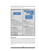

Table Of Contents
- Safe Usage
- General Description and Specifications
- Installation
- Operation
- User’s Guide
- The GroundAware™ user interface is an extended instance of GoogleMaps and is very intuitive to use by anyone who has experience with web-based mapping web sites. The traditional controls for zoom, pan, etc. work the same as with a standard GoogleMaps...

6
Electrical installation includes connecting the unit to a maximum 35 Watt, 24 VDC,
POE injector grounded alternating current source using a shielded ethernet cable.
Optionally, the unit may be powered through the switch in the interface sub-system as
described previously. Any additional switches utilized in the provision of power to the
system (e.g. installed by the customer) should be rated for the type and quality of power
specified.
Data connectivity installation includes connecting the unit to an IP4/IP6 network
through which connectivity to the server sub-system can be obtained. The unit may be
connected to the server sub-system network by several different means such as, wired
50directly, cellular, Wi-Fi extending antennas, etc. based on user requirements.
Given a basic understanding of system connectivity, installation and startup should
proceed as follows, given a basic three sub-system setup:
1. Mount the radar sub-system unit mechanically per the customer site
requirements and preparations.
2. Connect the radar sub-system unit to the IP4/IP6 server sub-system network
using means required by the customer site.
3. Connect and power-on the server sub-system on the same IP4/IP6 network as
the radar sub-system.
4. Connect the radar sub-system to commercial power that meets the previously
provided specifications.
5. Wait approximately 90 seconds before proceeding to the activities described in
Section 3.