
Microphone User Manual
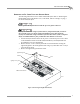

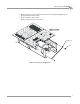
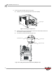
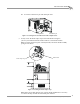
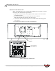
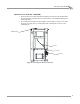
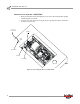
Table Of Contents
- Cover
- Copyright
- Table of Contents
- Air Brake and EEC Kit Installation
- Introduction
- Air Brake
- Removing the Drum Module Hood, Side Drum Cover, Center Panel, and Tire Carriage
- Removing the Pit Cover Plate and Upright Brace
- Installing the Air Brake Assembly
- Routing the Air Brake Cable
- Connecting the Shop Air-200i/250i
- Connecting the Shop Air-200iP/250iP
- Adjusting the Brake Pad Clearance
- Final Adjustments and Tests-200i/250i
- Final Adjustments and Tests-200iP/250iP
- EEC Finger Guards-200i/250i
- EEC Finger Guards-200iP/250iP
- Door Safety Switch
- Replacing the Drum Module Hood, Side Drum Cover, Center Panel, and Tire Carriage-200i/250i
- Replacing Pit Cover Plates and Upright Brace-200iP/250iP
Air Brake and EEC Kit Installation Guide for 200i/250i and 200iP/250iP Motorcycle Dynamometers
AIR BRAKE AND EEC KIT
Air Brake
12
8 Secure the brake assembly with two clevis pins.
8a Push the top clevis pin through the front of the assembly.
Figure 11: Inserting the Top Clevis Pin
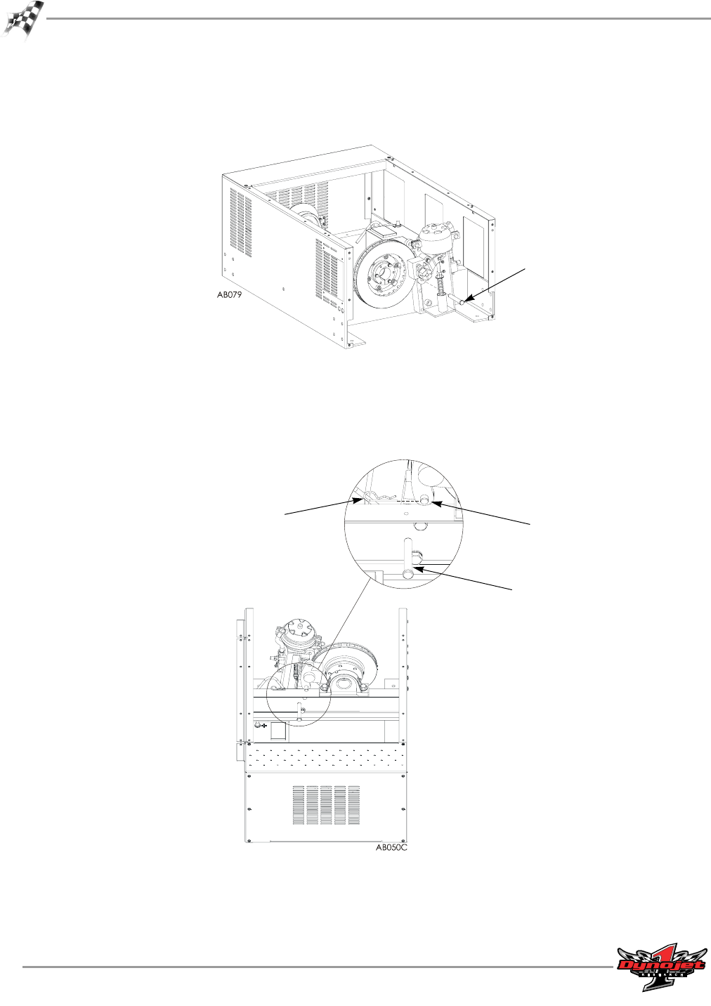
8b Push the bottom clevis pin through the back of the drum module frame and
the air brake assembly (drum side).
8c Secure the top clevis pin with a hair pin cotter.
Figure 12: Inserting the Bottom Clevis Pin and Top Hairpin Cotter
top clevis pin
bottom clevis pin
top hairpin cotter
top clevis pin