
Microphone User Manual
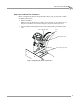
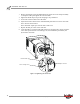
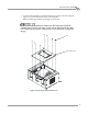
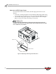
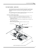
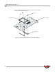
Table Of Contents
- Cover
- Copyright
- Table of Contents
- Air Brake and EEC Kit Installation
- Introduction
- Air Brake
- Removing the Drum Module Hood, Side Drum Cover, Center Panel, and Tire Carriage
- Removing the Pit Cover Plate and Upright Brace
- Installing the Air Brake Assembly
- Routing the Air Brake Cable
- Connecting the Shop Air-200i/250i
- Connecting the Shop Air-200iP/250iP
- Adjusting the Brake Pad Clearance
- Final Adjustments and Tests-200i/250i
- Final Adjustments and Tests-200iP/250iP
- EEC Finger Guards-200i/250i
- EEC Finger Guards-200iP/250iP
- Door Safety Switch
- Replacing the Drum Module Hood, Side Drum Cover, Center Panel, and Tire Carriage-200i/250i
- Replacing Pit Cover Plates and Upright Brace-200iP/250iP
Air Brake and EEC Kit Installation Guide for 200i/250i and 200iP/250iP Motorcycle Dynamometers
AIR BRAKE AND EEC KIT
Air Brake
18
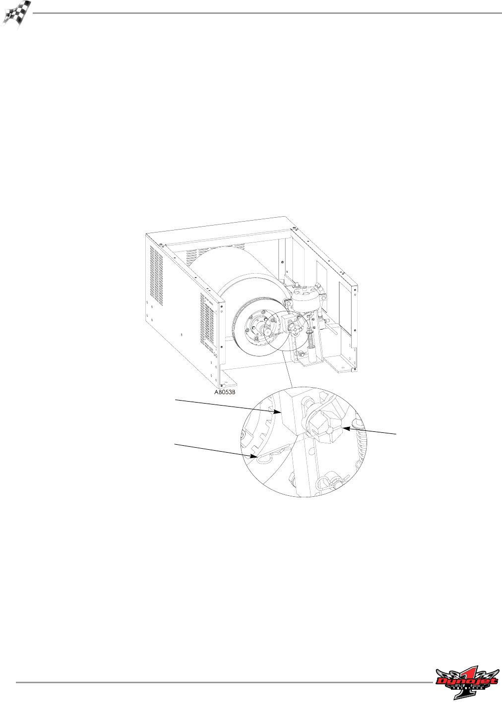
3 Remove the hairpin cotter and hand tighten the castle nut on the caliper assembly
to clamp the brake pads against the rotor and shim.
4 Tighten the brake caliper stop bolts torquing to 26 pounds/feet.
5 Loosen the castle nut and remove the shim.
6 Adjust the clearance between the outboard brake pad and rotor. Loosen the castle
nut to increase the clearance.
There should be equal space on both sides of the rotor.
7 Replace the hair pin cotter in the castle nut.
8 Cycle the brake to verify the brake pads release far enough so they do not touch the
rotor. If the pads touch the rotor during a run, the information provided by the
dyno will be inaccurate.
Figure 19: Tightening the Castle Nut
remove hairpin cotter
adjust castle nut
outboard brake pad