
Microphone User Manual
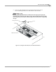
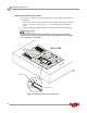


Table Of Contents
- Cover
- Copyright
- Table of Contents
- Air Brake and EEC Kit Installation
- Introduction
- Air Brake
- Removing the Drum Module Hood, Side Drum Cover, Center Panel, and Tire Carriage
- Removing the Pit Cover Plate and Upright Brace
- Installing the Air Brake Assembly
- Routing the Air Brake Cable
- Connecting the Shop Air-200i/250i
- Connecting the Shop Air-200iP/250iP
- Adjusting the Brake Pad Clearance
- Final Adjustments and Tests-200i/250i
- Final Adjustments and Tests-200iP/250iP
- EEC Finger Guards-200i/250i
- EEC Finger Guards-200iP/250iP
- Door Safety Switch
- Replacing the Drum Module Hood, Side Drum Cover, Center Panel, and Tire Carriage-200i/250i
- Replacing Pit Cover Plates and Upright Brace-200iP/250iP
INSTALLATION GUIDE
EEC Finger Guards—200iP/250iP
Version 1 Air Brake and EEC Kit Installation Guide for 200i/250i and 200iP/250iP Motorcycle Dynamometers
27
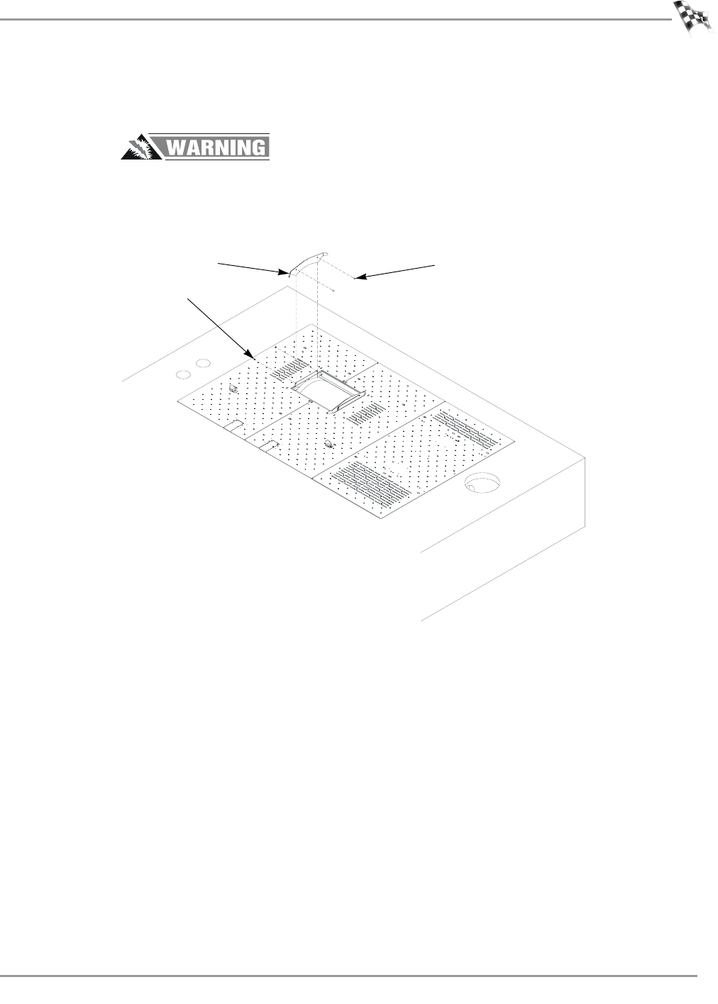
8 Secure the right drum guard to the drum guard mount using the two
1/4-20 x 5/8-inch pan head screws and locknuts removed earlier.
Do not operate the dynamometer without the EEC finger guards properly
installed. The gap between the finger guards and the drum must be less than
0.64 centimeters (0.25 inches). Refer to page 28 for instructions on adjusting
the gap.
Figure 27: Securing the Drum Guard to the Drum Guard Mount
FRONTOFDYNO
PD072
screw
drum guard mount
locknut