
Microphone User Manual
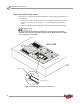

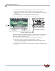


Table Of Contents
- Cover
- Copyright
- Table of Contents
- Air Brake and EEC Kit Installation
- Introduction
- Air Brake
- Removing the Drum Module Hood, Side Drum Cover, Center Panel, and Tire Carriage
- Removing the Pit Cover Plate and Upright Brace
- Installing the Air Brake Assembly
- Routing the Air Brake Cable
- Connecting the Shop Air-200i/250i
- Connecting the Shop Air-200iP/250iP
- Adjusting the Brake Pad Clearance
- Final Adjustments and Tests-200i/250i
- Final Adjustments and Tests-200iP/250iP
- EEC Finger Guards-200i/250i
- EEC Finger Guards-200iP/250iP
- Door Safety Switch
- Replacing the Drum Module Hood, Side Drum Cover, Center Panel, and Tire Carriage-200i/250i
- Replacing Pit Cover Plates and Upright Brace-200iP/250iP
INSTALLATION GUIDE
Door Safety Switch
Version 1 Air Brake and EEC Kit Installation Guide for 200i/250i and 200iP/250iP Motorcycle Dynamometers
31
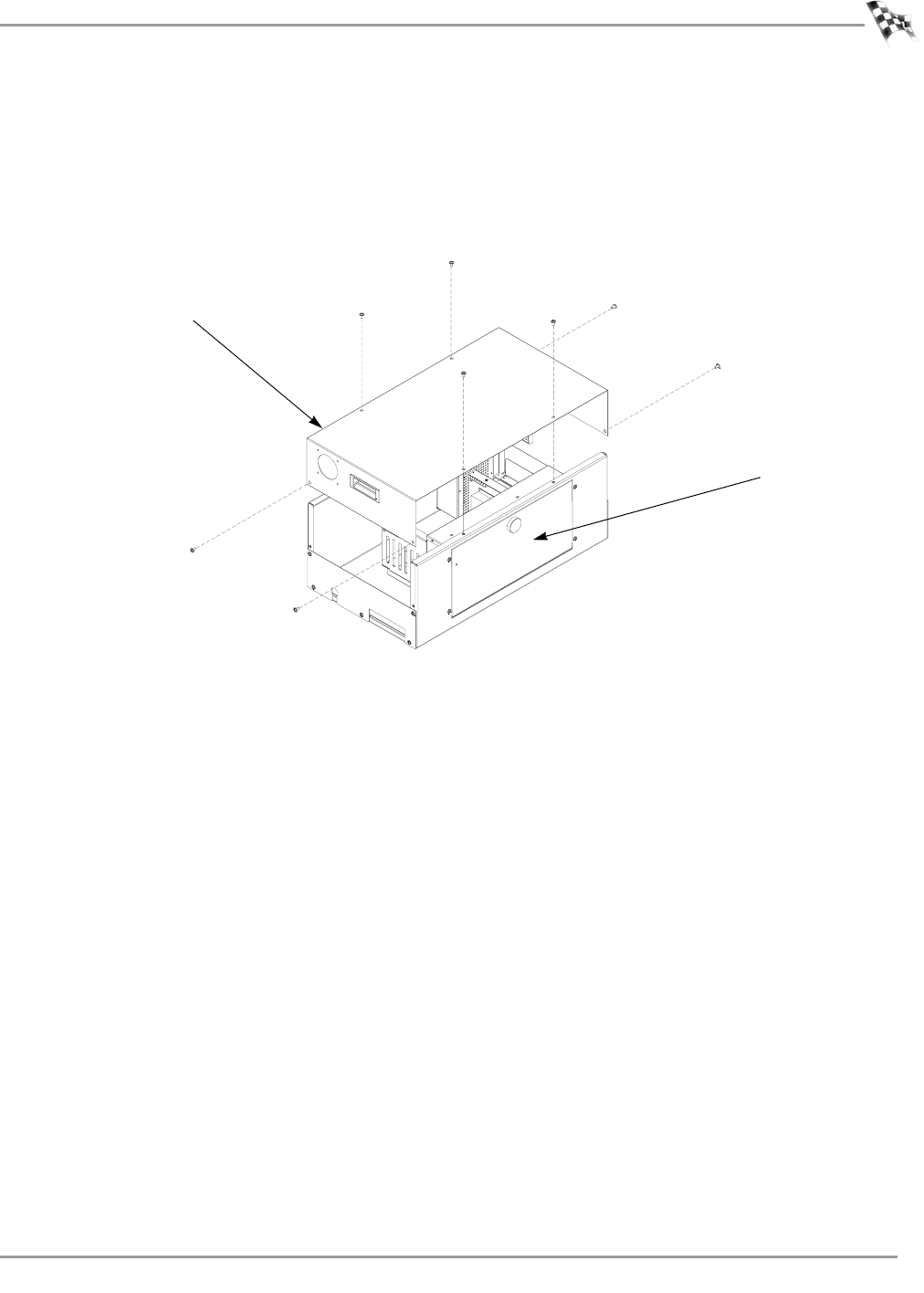
INSTALLING THE DOOR SAFETY SWITCH—200IP/250IP
1 Open the CPI front panel access and turn off the main breaker.
2 Unplug the dyno power cable.
3 Remove the eight button-head screws securing the CPI cover and set aside.
4 Remove the cover and set aside.
Figure 31: Accessing the CPI
PD027
cover
front panel access