
Microphone User Manual
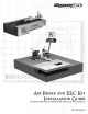
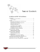

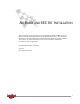
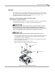
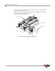
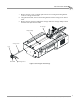
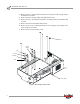
Table Of Contents
- Cover
- Copyright
- Table of Contents
- Air Brake and EEC Kit Installation
- Introduction
- Air Brake
- Removing the Drum Module Hood, Side Drum Cover, Center Panel, and Tire Carriage
- Removing the Pit Cover Plate and Upright Brace
- Installing the Air Brake Assembly
- Routing the Air Brake Cable
- Connecting the Shop Air-200i/250i
- Connecting the Shop Air-200iP/250iP
- Adjusting the Brake Pad Clearance
- Final Adjustments and Tests-200i/250i
- Final Adjustments and Tests-200iP/250iP
- EEC Finger Guards-200i/250i
- EEC Finger Guards-200iP/250iP
- Door Safety Switch
- Replacing the Drum Module Hood, Side Drum Cover, Center Panel, and Tire Carriage-200i/250i
- Replacing Pit Cover Plates and Upright Brace-200iP/250iP

Air Brake and EEC Kit Installation Guide for 200i/250i and 200iP/250iP Motorcycle Dynamometers
1
A
IR
B
RAKE
AND
EEC K
IT
I
NSTALLATION
This document provides instructions for installing the air brake and EEC Kit to the
model 200i/250i and 200iP/250iP motorcycle dynamometer (dyno). This document
will walk you through installing the air brake assembly, EEC finger guards, and door
safety switch. To ensure safety and accuracy in the procedures, perform the
procedures as they are described.
Document Part Number: 98123114
Version 1
Last Updated: 12-05-05