
Microphone User Manual
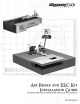
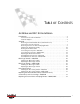

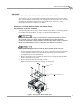
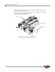
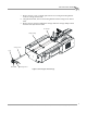
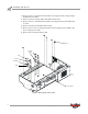
Table Of Contents
- Cover
- Copyright
- Table of Contents
- Air Brake and EEC Kit Installation
- Introduction
- Air Brake
- Removing the Drum Module Hood, Side Drum Cover, Center Panel, and Tire Carriage
- Removing the Pit Cover Plate and Upright Brace
- Installing the Air Brake Assembly
- Routing the Air Brake Cable
- Connecting the Shop Air-200i/250i
- Connecting the Shop Air-200iP/250iP
- Adjusting the Brake Pad Clearance
- Final Adjustments and Tests-200i/250i
- Final Adjustments and Tests-200iP/250iP
- EEC Finger Guards-200i/250i
- EEC Finger Guards-200iP/250iP
- Door Safety Switch
- Replacing the Drum Module Hood, Side Drum Cover, Center Panel, and Tire Carriage-200i/250i
- Replacing Pit Cover Plates and Upright Brace-200iP/250iP
Air Brake and EEC Kit Installation Guide for 200i/250i and 200iP/250iP Motorcycle Dynamometers
AIR BRAKE AND EEC KIT
Introduction
2
. . . . . . . . . . . . . . . . . . . . . . . . . . . . . . . . . . .
INTRODUCTION
The EEC Kit with Brake package consists of the EEC finger guards, air brake assembly,
and door safety switch. The air brake can also be purchased separately. The EEC finger
guards are a valuable safety device that allow you to regulate the distance between the
dyno chassis and the drum; the air brake quickly slows the drum’s rotation and locks
it for loading and unloading motorcycles; and the door safety switch provides an
added safety measure by automatically activating the dyno’s air brake when it is
triggered.
For more detailed information on the 200i/250i and 200iP/250iP motorcycle dynos,
refer to the Installation Guide for Model 200i/250i Motorcycle Dynamometers
(P/N 98220104) or the Installation Guide for Model 200iP/250iP Motorcycle Pit
Dynamometers (P/N 98229103).
CONVENTIONS USED IN THIS MANUAL
The conventions used in this manual are designed to protect both the user and the
equipment.
TECHNICAL SUPPORT
For assistance, please contact Dynojet Technical Support at 1-800-992-3525, or write
to Dynojet Research at 2191 Mendenhall Drive, North Las Vegas, NV 89081.
Visit us on the World Wide Web at www.dynojet.com where Dynojet provides state of
the art technical support, on-line shopping, 3D visualizations, and press releases
about our latest product line.
example of convention description
The Warning icon indicates potential harm to the
person performing a procedure and/or the
dynamometer equipment.
The Caution icon indicates a potential hazard to the
dynamometer equipment. Follow all procedures
exactly as they are described and use care when
performing all procedures.