
Microphone User Manual

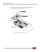


Table Of Contents
- Cover
- Copyright
- Table of Contents
- Air Brake and EEC Kit Installation
- Introduction
- Air Brake
- Removing the Drum Module Hood, Side Drum Cover, Center Panel, and Tire Carriage
- Removing the Pit Cover Plate and Upright Brace
- Installing the Air Brake Assembly
- Routing the Air Brake Cable
- Connecting the Shop Air-200i/250i
- Connecting the Shop Air-200iP/250iP
- Adjusting the Brake Pad Clearance
- Final Adjustments and Tests-200i/250i
- Final Adjustments and Tests-200iP/250iP
- EEC Finger Guards-200i/250i
- EEC Finger Guards-200iP/250iP
- Door Safety Switch
- Replacing the Drum Module Hood, Side Drum Cover, Center Panel, and Tire Carriage-200i/250i
- Replacing Pit Cover Plates and Upright Brace-200iP/250iP

Air Brake and EEC Kit Installation Guide for 200i/250i and 200iP/250iP Motorcycle Dynamometers
AIR BRAKE AND EEC KIT
Air Brake
14
ROUTING THE AIR BRAKE CABLE
Before proceeding with the rest of the air brake installation it is necessary to connect
the shop air and check the brake pad clearance.
1 Open the front panel of the control panel interface (CPI) to access the breakers
and Breakout board.
2 Route the air brake cable from the air brake solenoid to the CPI.
Note: The CPI end of the air brake cable splits in two.
3 Connect the cable with the two black wires to the Breakout board wiring block
labeled Brake.
4 Attach the 4-pin connector to port P7 on the CPI board.
Figure 15: Routing the Air Brake Cable
P7 on the
CPI board
brake wiring block
on breakout board