
Microphone User Manual


Table Of Contents
- Cover
- Copyright
- Table of Contents
- Air Brake and EEC Kit Installation
- Introduction
- Air Brake
- Removing the Drum Module Hood, Side Drum Cover, Center Panel, and Tire Carriage
- Removing the Pit Cover Plate and Upright Brace
- Installing the Air Brake Assembly
- Routing the Air Brake Cable
- Connecting the Shop Air-200i/250i
- Connecting the Shop Air-200iP/250iP
- Adjusting the Brake Pad Clearance
- Final Adjustments and Tests-200i/250i
- Final Adjustments and Tests-200iP/250iP
- EEC Finger Guards-200i/250i
- EEC Finger Guards-200iP/250iP
- Door Safety Switch
- Replacing the Drum Module Hood, Side Drum Cover, Center Panel, and Tire Carriage-200i/250i
- Replacing Pit Cover Plates and Upright Brace-200iP/250iP
INSTALLATION GUIDE
Door Safety Switch
Version 1 Air Brake and EEC Kit Installation Guide for 200i/250i and 200iP/250iP Motorcycle Dynamometers
29
. . . . . . . . . . . . . . . . . . . . . . . . . . . . . . . . . . .
DOOR SAFETY SWITCH
Safety requirements of your local country may require that a door safety switch is
installed. Be sure to follow the safety requirements specific to your country. The door
safety switch requires the air brake to work. This switch is located on the dyno room
door and is triggered when the pressure applied to it is released causing the air brake
to lock. This prevents the dyno from being used when the door is open.
Components attached to and within the dynamometer operate with potentially
lethal voltages. To provide the greatest assurance of safety, the AC power
cord(s) must be disconnected from the power source before servicing electrical
components or wiring. Disconnect all power cords before servicing electrical
components for the greatest assurance of safety.
INSTALLING THE DOOR SAFETY SWITCH—200I/250I
1 Turn off the main breaker inside the power distribution assembly door.
2 Unplug the dyno power cable.
3 Remove the tire carriage and center panel. Refer to “Removing the Drum Module
Hood, Side Drum Cover, Center Panel, and Tire Carriage” on page 3.
4 Remove the three screws securing the power distribution assembly cover and set
aside.
5 Remove the power distribution assembly cover and set aside.
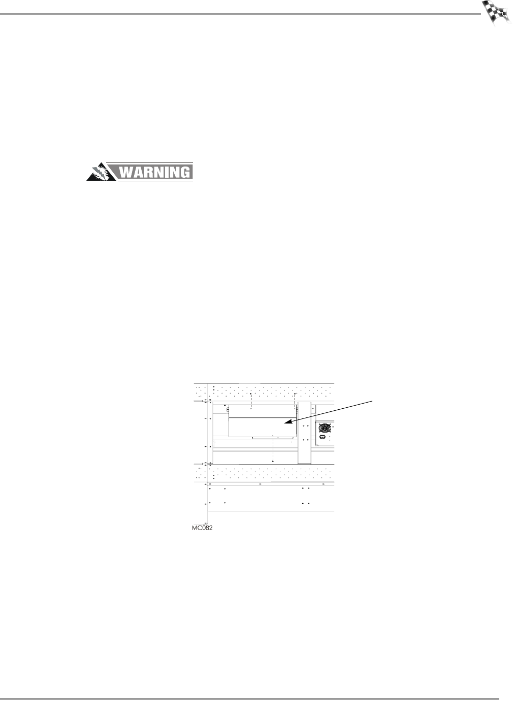
Figure 29: Removing the Power Distribution Assembly Cover
power distribution
assembly cover