
Microphone User Manual


Table Of Contents
- Cover
- Copyright
- Table of Contents
- Air Brake and EEC Kit Installation
- Introduction
- Air Brake
- Removing the Drum Module Hood, Side Drum Cover, Center Panel, and Tire Carriage
- Removing the Pit Cover Plate and Upright Brace
- Installing the Air Brake Assembly
- Routing the Air Brake Cable
- Connecting the Shop Air-200i/250i
- Connecting the Shop Air-200iP/250iP
- Adjusting the Brake Pad Clearance
- Final Adjustments and Tests-200i/250i
- Final Adjustments and Tests-200iP/250iP
- EEC Finger Guards-200i/250i
- EEC Finger Guards-200iP/250iP
- Door Safety Switch
- Replacing the Drum Module Hood, Side Drum Cover, Center Panel, and Tire Carriage-200i/250i
- Replacing Pit Cover Plates and Upright Brace-200iP/250iP
Air Brake and EEC Kit Installation Guide for 200i/250i and 200iP/250iP Motorcycle Dynamometers
AIR BRAKE AND EEC KIT
Door Safety Switch
30
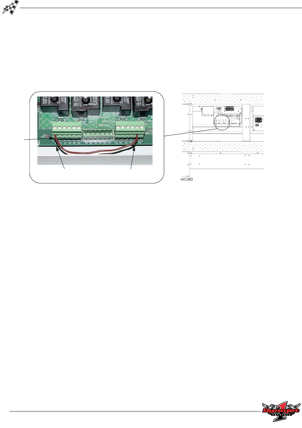
6 Loosen the screws that hold the jumper wires in place and remove the wire.
7 Route the black and yellow wire from the safety switch through the dyno.
Make sure the switch will not get caught in any moving components or chafed on
any edges.
8 Attach the yellow wire to the 1A position on the J2 connector.
9 Attach the black wire to the 6B position on the J4 connector.
Figure 30: Wiring the Safety Switch
10 Replace the power distribution assembly cover using the screws removed earlier.
11 The door safety switch needs to be mounted at the entry of the dyno room.
12 Plug the dyno into the power outlet.
13 Turn on the main breaker inside the power distribution assembly door.
14 Open the door safety switch by allowing the plunger to extend.
The air brake should be applied holding the drum and the status light on the
Control Panel will be flashing.
15 Depress the safety switch and the air brake will release and the status light will be
on steady.
black wire to 6B
on J4 connector
yellow wire to 1A
on J2 connector
remove
jumper
wire