
Microphone User Manual


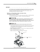


Table Of Contents
- Cover
- Copyright
- Table of Contents
- Air Brake and EEC Kit Installation
- Introduction
- Air Brake
- Removing the Drum Module Hood, Side Drum Cover, Center Panel, and Tire Carriage
- Removing the Pit Cover Plate and Upright Brace
- Installing the Air Brake Assembly
- Routing the Air Brake Cable
- Connecting the Shop Air-200i/250i
- Connecting the Shop Air-200iP/250iP
- Adjusting the Brake Pad Clearance
- Final Adjustments and Tests-200i/250i
- Final Adjustments and Tests-200iP/250iP
- EEC Finger Guards-200i/250i
- EEC Finger Guards-200iP/250iP
- Door Safety Switch
- Replacing the Drum Module Hood, Side Drum Cover, Center Panel, and Tire Carriage-200i/250i
- Replacing Pit Cover Plates and Upright Brace-200iP/250iP
INSTALLATION GUIDE
Air Brake
Version 1 Air Brake and EEC Kit Installation Guide for 200i/250i and 200iP/250iP Motorcycle Dynamometers
5
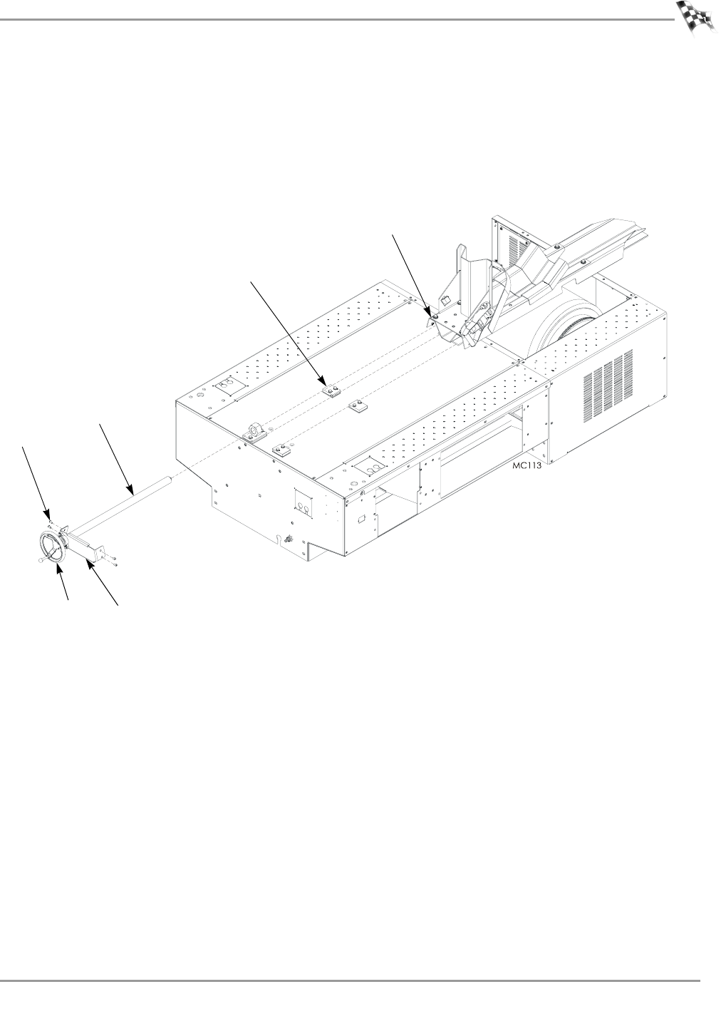
7 Remove the four 1/4-20 x 5/8-inch pan head screws securing the bearing bracket
to the tire carriage and set aside.
8 Using the hand crank, unscrew the bearing bracket and the carriage screw and set
aside.
9 Remove the tire carriage by sliding the carriage under the carriage clamps toward
the back of the dyno and set aside.
Figure 3: Removing the Tire Carriage
hand crank
carriage screw
bolt
carriage clamp
tire carriage
bearing bracket