
Microphone User Manual


MOBILE BASE INSTALLATION
Eddy Current Brake
Version 1 Mobile Base Installation Guide
1-13
. . . . . . . . . . . . . . . . . . . . . . . . . . . . . . . . . . .
EDDY CURRENT BRAKE
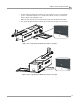
This section describes how to align the eddy current brake with the dyno, align the
couplers, and attach the cables from the eddy current brake to the Theta Controller
and Breakout board.
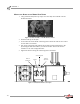
For more information about the eddy current brake, refer to the Eddy Current Brake
Installation Guide (P/N 98226100).
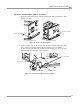
ALIGNING THE EDDY CURRENT BRAKE
Eddy current brake and coupler alignment is very important. You must follow
these instructions very carefully to ensure proper alignment and function.
Dynojet will not warranty any coupler that is damaged due to improper
installation.
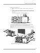
1 Place a straight edge with a notch across the apex of the drum with the notch
across the eddy current brake.
2 Using the straight edge as a guide, measure the distance to the collars on the axle
shaft of the eddy current brake (not the black bearing lock collars).
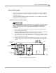
3 Place shims between the mobile base frame and the eddy current brake or dyno
until the collars are 7 19/32-inch (19.288 cm) +/- 1/16-inch (1.58 mm) down from
the top of the drum on the dyno.
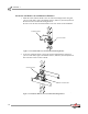
4 Torque all the bolts securing the connecting arms to the dyno and to the eddy
current brake to 33 ft. lb. (45 N-m). Verify the height and make sure nothing has
moved.
Figure 1-19: Align the Eddy Current Brake
7 19/32 inches
(19.288 cm)
eddy current
brake
collars on axle shaft
straight edge
with notch
connecting arms
drum